Marine composite superstructure bulkhead and preparation method thereof

A composite material and superstructure technology, applied in hull bulkheads, ship construction, chemical instruments and methods, etc., can solve the problems of heavy building weight, insufficient bulletproof plate protection and electromagnetic stealth performance, fatigue fracture, etc.

Active Publication Date: 2020-10-20
NAVAL UNIV OF ENG PLA
View PDF14 Cites 4 Cited by
  • Summary
  • Abstract
  • Description
  • Claims
  • Application Information

AI Technical Summary

Problems solved by technology

[0007] The technical problem to be solved by the present invention lies in the fact that the traditional ship steel superstructure is heavy, the aluminum alloy superstructure has a low melting point and is prone to fatigue fracture at the connection with the steel structure, and the existing composite material bulletproof plate has insufficient protection and electromagnetic stealth performance The problem is to provide a lightweight, high-strength marine composite material superstructure bulkhead and its preparation method, which can meet the requirements of the impact load of splashing water waves, and realize the defense against the invasion of 100-1500m / s and 1g-20g cube fragments. The reflectivity in the range of 2~8GHz is lower than -10dB, and the reflectivity in the range of 8~18GHz is lower than -18dB Electromagnetic stealth performance

Method used


Image

  • Marine composite superstructure bulkhead and preparation method thereof
  • Marine composite superstructure bulkhead and preparation method thereof
  • Marine composite superstructure bulkhead and preparation method thereof

Examples


Embodiment Construction

[0048] In order to have a clearer understanding of the technical features, purposes and effects of the present invention, the specific implementation manners of the present invention will now be described in detail with reference to the accompanying drawings.

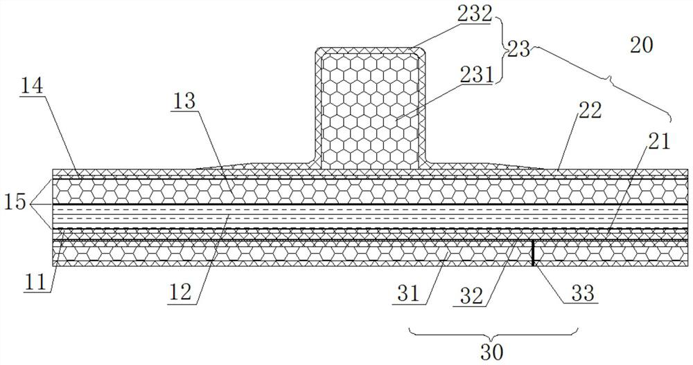
[0049] Such as figure 1 As shown, a marine composite material superstructure bulkhead provided by the present invention includes a protective sandwich structure 10 , a reinforcement structure 20 and a radar stealth structure 30 .

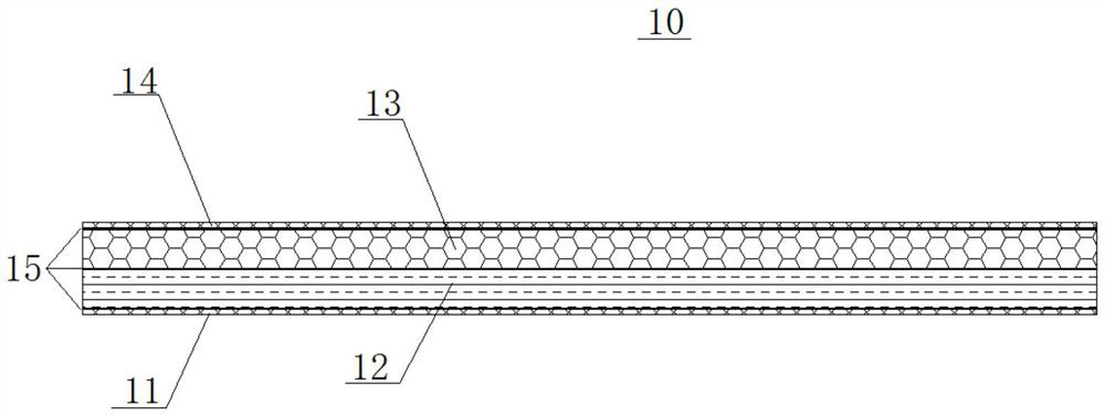
[0050] Such as figure 2 As shown, the protective sandwich structure 10 includes a lower skin 11, an ultra-high molecular weight polyethylene armor plate 12, a PVC foam layer 13 and an upper skin 14 arranged sequentially from bottom to top, and the layers are bonded by adhesive into one.

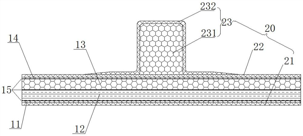
[0051] Such as Figure 3-4 As shown, the reinforcement structure 20 includes a bottom FRP layer 21 , a surface FRP layer 22 , PVC foam reinforcement ribs 231 and a glass fiber reinforced skin 232 . The ...


PUM

PropertyMeasurementUnit
densityaaaaaaaaaa
compressive strengthaaaaaaaaaa
compressive modulusaaaaaaaaaa

Abstract

The invention relates to a marine composite superstructure bulkhead, which comprises a protective sandwich structure and a reinforcing structure. The protective sandwich structure comprises a lower-layer skin, an ultra-high molecular weight polyethylene armor plate, a PVC foam layer and an upper-layer skin, which are sequentially arranged from bottom to top, and all layers are bonded into a wholethrough an adhesive. The reinforcing structure comprises a bottom glass fiber reinforced plastic layer, a surface glass fiber reinforced plastic layer, PVC foam reinforced ribs and a glass fiber reinforced skin. The bottom glass fiber reinforced plastic layer is laid on the outer surface of the lower-layer skin of the protective sandwich structure; the surface glass fiber reinforced plastic layeris laid on the outer surface of the upper-layer skin, the PVC foam reinforced ribs are installed on the outer surface of the surface glass fiber reinforced plastic layer, and the glass fiber reinforced skin wraps the surfaces of the PVC foam reinforced ribs. The protective sandwich structure and the reinforcing structure are formed by adopting a vacuum flow guide integrated forming process. The marine composite superstructure bulkhead can meet the requirement on the impact load of splashed water spray, penetration of cubic fragments with a speed of 100-1500 m/s and a mass of 1-20 g can be defended, and the electromagnetic stealth performance is: the reflectivity within a range of 2-8 GHz is lower than -10 dB, and the reflectivity within the range of 8-18 GHz is lower than -18 dB.

Description

technical field [0001] The invention relates to the technical field of ship bulletproof protection and radar stealth, in particular to a composite material superstructure bulkhead for a ship and a preparation method thereof. Background technique [0002] Large and medium-sized surface ships have become an important symbol and main assault force of various naval powers. They are highly integrated maritime combat weapon systems of various forces. Their special strategic and tactical status make them inevitably the main attack targets of the enemy. [0003] The passive protection structure of the ship is the last line of defense of the ship. The density of the metal armor material used in the initial stage of the ship is too high. Extensive use of armor steel will increase the weight of the hull, weaken the combat effectiveness and mobility of the ship, and make it difficult to achieve protection. Lightweight design requirements for structures. Aluminum alloy has a low melting...

Claims


Application Information

Patent Timeline
Patent Type & Authority Applications(China)
IPC IPC(8): B32B3/30B32B7/12B32B27/08B32B27/30B32B27/32B32B33/00B29C70/34B63B3/56
CPCB32B5/18B32B27/08B32B27/32B32B7/12B32B3/30B32B33/00B29C70/342B63B3/56B32B2266/0235B32B2307/558B32B2307/72B32B2307/552B32B2307/546B32B2307/102B32B2307/304B32B2605/12B29L2031/307Y02A30/30
Inventor 李永清李典侯海量郑羽鄢柳柳李怿吴伟姜安邦
Owner NAVAL UNIV OF ENG PLA
Why Eureka
Try Eureka