Process for improving coloring rate of polyester printing
A printing and crafting technology, applied in the field of clothing fabrics, can solve the problems of inability to guarantee the printing coloring rate, affecting the health of users, and inability to accurately express the excellent effect of pretreatment.
Active Publication Date: 2020-10-20
宣城凯欧纺织有限公司
6 Cites 0 Cited by
AI-Extracted Technical Summary
Problems solved by technology
Usually, the polyester fabric is printed to improve the aesthetics of the fabric to achieve the goal, but in the printing process, due to the characteristics of the polyester fabric itself, the coloring rate is not high during printing, and the color depth of the printed polyester fabric is not good. , urgently need to solve
[0003] There are also some technical solutions in the prior art, such as the Chinese patent with application number CN201911082980.3, which includes step S1: perform quality inspection on polyester fabric, and perform antistatic treatment; step S2: perform pretreatment on polyester fabric; step S3 : Sizing the polyester fabric; step S4: washing the polyester fabric: washing the steamed polyester fabric with a washing agent; step S5: winding the polyester fabric on a hanger to make a flat screen screen; The flat screen is scraped and drawn to form a slurry p...
Abstract
The invention belongs to the technical field of clothing fabrics, and particularly relates to a process for improving the coloring rate of polyester printing. The process includes the following stepsthat S1, after the surface of a polyester fabric is cleaned and mercerized, the fabric is rolled onto a material roller 3; S2, the fabric treated in the step S1 is transported into a sueding device, and the surface of the fabric is sueded; and S3, the fabric treated in the step S2 is printed to obtain a finished product. The process can effectively improve the coloring rate of polyester fabric printing, the color depth on the printed fabric is increased, and the printing effect is enhanced.
Application Domain
Fibre typesUltrasonic/sonic fibre treatment +2
Technology Topic
PolyesterPolymer chemistry +3
Image
Examples
- Experimental program(1)
Example Embodiment
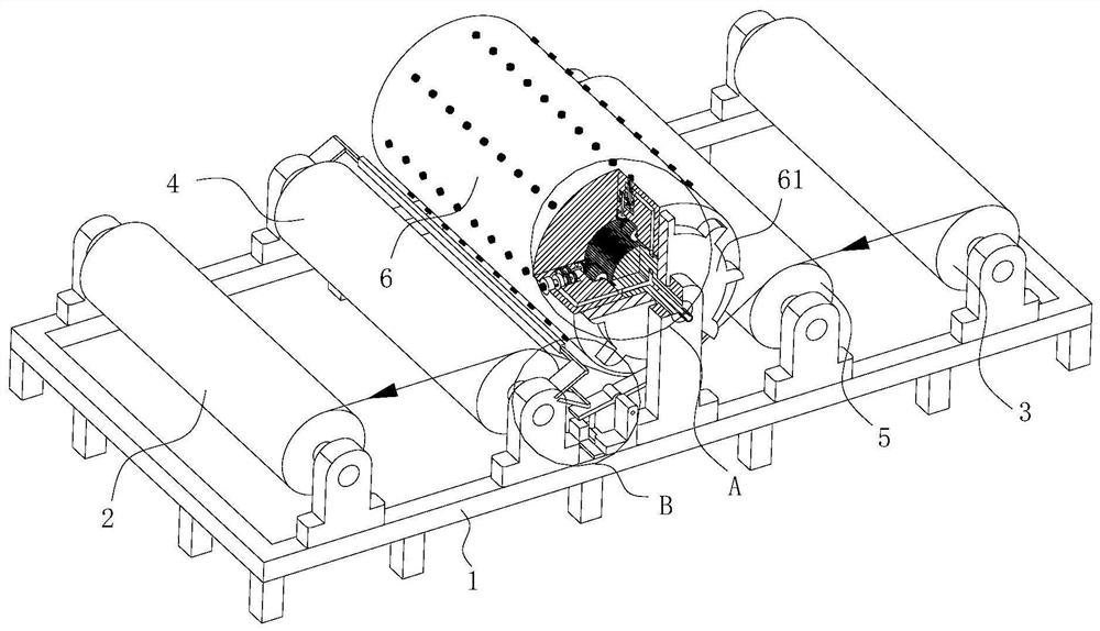
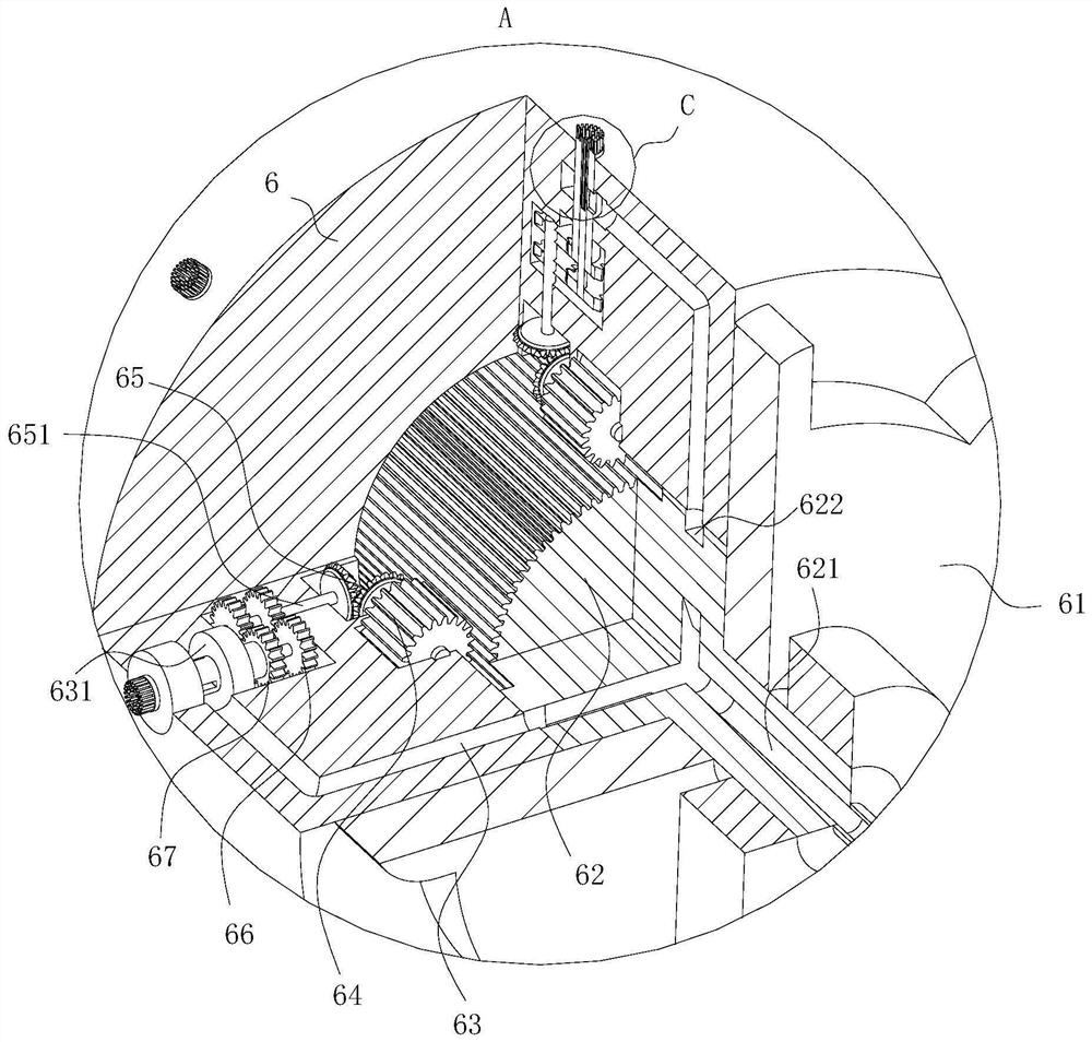
[0038] As an embodiment of the present invention, the grinding roller 6 is provided with an installation cavity 3; the top of the rotating shaft 651 is located in the installation cavity 3; the installation cavity 3 is installed with a gear train 1 66 and a gear train 2 67 The distance between the gear train one 66 and the top of the rotating shaft 651 is greater than the distance between the gear train two 67 and the top end of the rotating shaft 651; the transmission ratio between the gear train one 66 and the gear train two 67 is different; the gear train one 66 and the gear train 267 are powered by the rotating shaft 651; the inner shaft 681 is installed inside the outer shaft 68; The lower ends of the shaft 68 and the inner shaft 681 are inserted into the third mounting cavity; the outer shaft 68 is driven by the rotating shaft 651 through the second gear train 67; the inner shaft 681 is driven by the rotating shaft 651 through the gear train 1 66;
[0039] During operation, since the outer shaft 68 and the inner shaft 681 are simultaneously connected to the rotating shaft 651 through the first gear 66 and the second gear 67 with different transmission ratios, during the rotation of the outer shaft 68 and the inner shaft 681, the inner shaft 681 and the The rotation speed of the outer shaft 68 is inconsistent, causing relative movement between the inner shaft 681 and the outer shaft 68. When the top ends of the outer shaft 68 and the inner shaft 681 rotate with the grinding roller 6 to grind the surface of the fabric, due to the There is relative movement between the outer shaft 68 and the inner shaft 681. Therefore, during the advancement of the fabric, the inner shaft 681 and the outer shaft 68 will grind the same area on the fabric in different directions, effectively improving the quality of the hair after sanding. Effect, increase the dyeing depth and coloring rate during the dyeing after sanding, and at the same time, through the sanding of the inner shaft 681 and the outer shaft 68 with relative motion, the tangling of the fluff on the surface of the fabric after sanding can be effectively avoided. The knot can make the fluff relatively fluffy and dispersed, which is convenient for subsequent dyeing and printing treatment, and improves the effect of dyeing and printing treatment.
[0040] As an embodiment of the present invention, the top end of the inner shaft 681 is rounded; the top end of the inner shaft 681 exceeds the top end of the outer shaft 68; the top end of the outer shaft 68 is provided with bristles 684; the bristles 684 The top of the shaft exceeds the top of the inner shaft 681;
[0041] During operation, since the top of the bristles 684 installed on the outer shaft 68 exceeds the top of the inner shaft 681, when grinding the surface of the fabric, the bristles 684 on the outer shaft 68 first contact the surface of the fabric, and the bristles 684 are used to polish the surface of the fabric. In the first sanding, when the fibers on the surface of the fabric are picked up by the bristles 684, the lifted fibers will contact the top of the inner shaft 681, and the fabric will be sanded again through the inner shaft 681 to ensure a good sanding effect. , At the same time, since the top of the inner shaft 681 is made of metal material, the initial sanding through the bristles 684 can avoid the large impact on the fabric caused by the metal sanding head on the surface of the fabric, and keep the strength of the fabric itself as much as possible. Extend the service life of the fabric. At the same time, after the secondary sanding through the inner shaft 681, the consistency of the fluff produced by the sanding can be ensured, and the fibers that make up the fluff can be destroyed to a certain extent by the metal sanding head to improve the subsequent dyeing. , When printing, the coloring rate and color depth of the fabric.
[0042] As an embodiment of the present invention, the inner shaft 681 is provided with a third channel 683; the outlet of the third channel 683 is located at the top end of the inner shaft 681; the outer shaft 68 is provided with a rectangular groove 682; the inner shaft 681 is provided with a through hole; the through hole is located below the rectangular groove 682; the rectangular groove 682 communicates with the channel 3 683 through the through hole; a cavity 631 is opened in the sanding roller 6; The part where the rectangular groove 682 is opened is located in the cavity 631; the sanding roller 6 is provided with a channel two 63; the outlet of the channel two 63 is located at the part of the gear shaft 62 where the bump is in contact with the sanding roller 6; An annular groove 622 is formed in the middle of the projection on the gear shaft 62; the passage two 63 can be communicated with the annular groove 622; a passage one 621 is opened in the gear shaft 62; The passage one 621 is passed into the outside high temperature steam;
[0043] During operation, when the sanding roller 6 grinds the surface of the fabric, the high-temperature steam introduced from the outside enters the annular groove 622 through the first channel 621, and then enters the second channel 63 through the annular groove 622, and then enters the second channel 63. The high-temperature steam in the cavity 631 enters the cavity 631, and the high-temperature steam in the cavity 631 enters the channel three 683 through the through hole under the rectangular groove 682, and finally is ejected from the outlet of the channel three 683 at the top of the inner shaft 681, and passes through the outside. The incoming high-temperature steam scours the fabric to form an ironing effect similar to an iron. During the sanding process, the high-temperature steam ensures that the fabric is straight and prevents the fabric from wrinkling and twisting during the sanding operation. The appearance of the fabric and the effect of sanding, at the same time, through the high-temperature steam introduced, the surface humidity of the fabric is increased, and the friction between the sanding roller 6 and the fabric can be relatively improved during sanding, so that the fabric can be sanded. It can achieve a better sanding effect, and at the same time, the fluff produced by the sanding can be attached to the surface of the fabric to avoid the tangling of the fluff and affect the subsequent dyeing and printing processes.
[0044] As an embodiment of the present invention, an electrode 73 is installed on the first bracket 11; there are two motors, which are symmetrically installed on the upper and lower sides of the fabric; the frame 1 is installed with a bracket three 13; the bracket A dial 72 is installed on the third 13; the dial 72 is hinged on the bracket three 13; the end of the bracket three 13 close to the electrode 73 is connected with an elastic cord 71; the other end of the elastic cord 71 is fixedly connected to the bracket three 13; a cam 61 is installed on the end face of the grinding roller 6; the cam 61 is in contact with the end of the dial 72 away from the electrode 73; a bracket 2 12 is installed on the frame 1; The piezoelectric ceramic 7 is installed; the two poles of the piezoelectric ceramic 7 are respectively connected to the two electrodes 73; the piezoelectric ceramic 7 is located directly below the end of the dial 72 close to the electrode 73; the dial 72 can be tapped Piezoelectric ceramics 7;
[0045] When working, with the rotation of the grinding roller 6, the cam 61 installed on the end face of the grinding roller 6 also starts to rotate, and the movement of the dial plate 72 is driven by the rotation of the cam 61. Therefore, when the dial plate 72 passes over the protruding part of the cam 61, the dial plate 72 will quickly rebound under the action of the elastic rope 71, thereby hitting the piezoelectric ceramic 7, causing the piezoelectric ceramic 7 to generate current, At the same time, the generated current generates a discharge between the two electrodes 73. Since the electrodes 73 are located on the upper and lower sides of the fabric, the discharge current will pass through the fabric to produce a plasma treatment effect on the fabric. 7, the current is small, the safety is high, and safety accidents are not easy to occur. At the same time, through the treatment of the current, the surface of the fluff produced by the surface sanding of the fabric is subjected to plasma etching, forming cracks, which is conducive to the subsequent processing and improves the dyeing and printing. The tinting rate and color depth of the fabric.
[0046] As an embodiment of the present invention, a fleece suction hood is provided directly above the brushing roller 6; the fleece suction hood is connected with a negative pressure fan through a pipeline; a brush is arranged in the fleece suction hood; the brush Contact the surface of the grinding roller 6;
[0047] When working, the short fibers produced by grinding are taken away by the velvet cover to ensure the clean and tidy production environment, and at the same time, the harm of the small fibers to the workers' bodies is avoided, and the safety is improved.
[0048] The specific workflow is as follows:
[0049] When working, install the processed fabric on the feed roller 3, and then pass the fabric through the guide roller 2 5, the sanding roller 6, and the guide roller 1 4 in turn, so that the fabric is collected by the winding roller 2. When the fabric moves , start the motor, and drive the sanding roller 6 to run through the motor. Since the sanding roller 6 and the fabric move in the opposite direction, there is relative movement between the sanding roller 6 and the fabric, and the surface of the fabric is sanded by the sanding roller 6. When the sanding roller 6 rotates, since the gear shaft 62 in the sanding roller 6 is fixed on the frame 1, the relative rotation between the sanding roller 6 and the gear shaft 62 occurs, and the gear one 64 installed in the sanding roller 6 be driven, so that the gear one 64 rotates. After the gear one 64 rotates, it drives the bevel gear train 65 to start to rotate, and then drives the rotating shaft 651 to rotate through the bevel gear train 65. Since the outer shaft 68 is installed on the rotating shaft 651, the outer The shaft 68 starts to rotate, so that when the sanding roller 6 is running, the sanding head on the surface of the sanding roller 6 also rotates due to the rotation of the outer shaft 68; The second gear train 67 is connected to the rotating shaft 651 at the same time. Therefore, during the rotation of the outer shaft 68 and the inner shaft 681, the rotation speeds of the inner shaft 681 and the outer shaft 68 are inconsistent, so that the relative relationship between the inner shaft 681 and the outer shaft 68 occurs. When the sanding roller 6 grinds the surface of the fabric, the high-temperature steam introduced from the outside enters the annular groove 622 through the first channel 621, and then enters the second channel 63 through the annular groove 622, and then the steam in the second channel 63 The high-temperature steam enters the cavity 631, and the high-temperature steam in the cavity 631 enters the channel three 683 through the through hole under the rectangular groove 682, and finally ejects from the outlet of the channel three 683 at the top of the inner shaft 681; The rotation of the hair roller 6, the cam 61 installed on the end face of the hair roller 6 also starts to rotate, and the movement of the dial plate 72 is driven by the rotation of the cam 61. Since the end of the dial plate 72 close to the electrode 73 is installed with an elastic rope 71, therefore, When the dial plate 72 passes over the convex part on the cam 61, the dial plate 72 will rebound quickly under the action of the elastic rope 71, thereby hitting the piezoelectric ceramic 7, so that the piezoelectric ceramic 7 generates a current, and at the same time, the generated current is in the A discharge is generated between the two electrodes 73. Since the electrodes 73 are located on the upper and lower sides of the fabric, the discharge current will pass through the fabric.
PUM


Description & Claims & Application Information
We can also present the details of the Description, Claims and Application information to help users get a comprehensive understanding of the technical details of the patent, such as background art, summary of invention, brief description of drawings, description of embodiments, and other original content. On the other hand, users can also determine the specific scope of protection of the technology through the list of claims; as well as understand the changes in the life cycle of the technology with the presentation of the patent timeline. Login to view more.