Hoisting method for modular vault-type space tube truss steel structure system building

A hoisting method and a pipe truss technology, which are applied in construction, building structure, processing of building materials, etc., can solve the problems of high safety risk, many high-altitude operations, and many procedures.

Inactive Publication Date: 2020-10-20
沈阳科维润工程技术有限公司
View PDF9 Cites 3 Cited by
  • Summary
  • Abstract
  • Description
  • Claims
  • Application Information

AI Technical Summary

Problems solved by technology

[0003] In order to solve the above-mentioned problems of many procedures, high-altitude operations, high safety risks and low efficiency in the process of truss hoisting and tie rod installation, the present invention provides a modular hoisting method for a steel structure system of arched space tube trusses. Most of the installation work is done

Method used


Image

  • Hoisting method for modular vault-type space tube truss steel structure system building
  • Hoisting method for modular vault-type space tube truss steel structure system building
  • Hoisting method for modular vault-type space tube truss steel structure system building

Examples


Embodiment 1

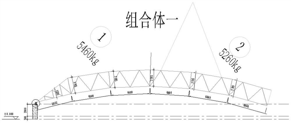
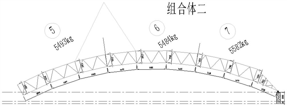
[0037] The 2 steel truss module units are pre-assembled on the ground to form 7 modular units, and then the 7 modular units are assembled on the ground, unit 1 and unit 2 are assembled on the ground to form a module combination 1, Assemble unit body 5, unit body 6, and unit body 7 on the ground into module assembly 2, and assemble unit body 3 and unit 4 on the ground into module assembly 3, using two 80t crawler cranes and one 220t truck crane respectively. Hanging.

[0038] Hanging point setting: 4 hanging points are set on each module combination, and the hanging points are set on the upper chord main pole node of the truss with a vertical pole. In order to ensure that the combination is evenly stressed during hoisting and ascent, the front and rear hoisting points on each truss are dynamically adjusted with a steel wire rope (length 20m) through a fixed pulley set on the balance beam. The wire ropes of the lifting points on the trusses on both sides are connected with the ...

Embodiment 2

[0042] The 2 steel truss module units are pre-assembled on the ground and assembled into 7 module units, and then the 7 module units are assembled on the ground, and the module unit 1, the module unit 2 and the module unit 3 are assembled. Assemble the module assembly 1 on the ground, assemble the module unit body 4, the module unit body 5, the module unit body 6, and the module unit body 7 into the module assembly body 2 on the ground, and use a 160t crawler crane and a 200t truck crane respectively The machine is hoisted.

[0043] Hanging point setting: Set 4 hanging points on the module assembly 1, and the hanging points are set on the upper chord main pole node of the truss with a vertical pole. In order to ensure that the combination is evenly stressed during hoisting and ascent, the front and rear lifting points on each truss are dynamically adjusted with a steel wire rope (20m in length, 25mm in diameter) through a fixed pulley set on the balance beam. The wire ropes o...


PUM


Abstract

The invention belongs to the technical field of steel structure building hoisting methods, and particularly relates to a hoisting method for a modular vault-type space tube truss steel structure system building. A modular unit of two or more steel trusses is divided into combinations with two or three sections, a ground splicing mode is adopted, all modular assemblies with steel structures are assembled into a plurality of unit bodies, then the several unit bodies are spliced into a combination, and a hoisting mode of simultaneous closing of the multiple high-altitude trusses is adopted. The aloft work processes such as truss and tie bar hoisting and high-altitude tie bar screwing and high-strength bolt fastening are reduced, the using machine-team of a crane is greatly reduced, because ofthe hoisting mode of the combinations, the working face is large, after multi-station truss hoisting is completed, the safe stability can be good, boundary dimension deformation of the trusses is small, all hole positions of high-strength bolts can be ensured, and the later bar filling process is facilitated.

Description

technical field [0001] The invention belongs to the technical field of steel structure building hoisting methods, and in particular relates to a modular arch space pipe truss steel structure system building hoisting method and building, which are applied to large-span modules of material storage yard closure projects in smelting industries, wharfs, and mining areas Hoisting of modernized arch space tube truss steel structure system building. Background technique [0002] At present, the traditional hoisting method of grid or truss steel structure buildings is to adopt the hoisting method of portal steel frame or steel grid frame step by step. After the second truss and the anchor rope are pulled up, the middle tie bars are assembled at high altitude to complete the installation of the two trusses. This method has many procedures, high-altitude operations, low efficiency, and high labor intensity. After the single truss is hoisted, the external dimension will be greatly defo...

Claims


Application Information

Patent Timeline
IPC IPC(8): E04G21/16E04C3/40
CPCE04C3/40E04G21/162
Inventor 黄奎生王九州吕胜兵樊洞齐王洁斌周振飞毛刚
Owner 沈阳科维润工程技术有限公司
Why Eureka
Try Eureka