
High-capacity embedded conical-surface synchronizer and transmission

An embedded and synchronizer technology, applied in the direction of clutches, friction clutches, mechanically driven clutches, etc., can solve difficulties, increase gear bending fatigue and contact fatigue life and other problems

Pending Publication Date: 2020-10-20
SHAANXI FAST AUTO DRIVE GROUP CO LTD
View PDF0 Cites 1 Cited by
  • Summary
  • Abstract
  • Description
  • Claims
  • Application Information

AI Technical Summary

Problems solved by technology

[0002] With the development of high-horsepower and high-torque manual transmissions, it has become extremely difficult for traditional synchronizers to achieve smaller transmission lengths through smaller installation distances and shift strokes, or to reduce the installation of synchronizers when the length of the transmission remains the same. It is also difficult to implement measures to increase the gear width and increase the bending fatigue and contact fatigue life of the gear.

Method used


Image

  • High-capacity embedded conical-surface synchronizer and transmission
  • High-capacity embedded conical-surface synchronizer and transmission
  • High-capacity embedded conical-surface synchronizer and transmission

Examples


Embodiment 1

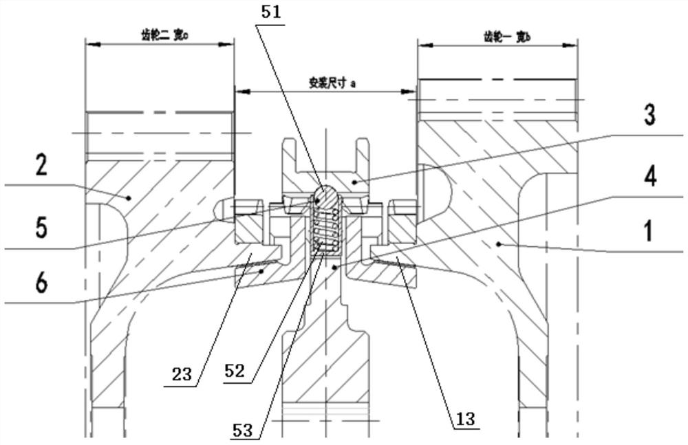
[0099] Such as figure 1 As shown, the synchronizer of this embodiment is an embedded single-cone synchronizer, which is arranged between the first gear assembly 1 and the second gear assembly 2. The first gear assembly 1 is composed of the first gear 11 and the first gear assembly. The second gear assembly 2 is composed of the second gear 21 and the second combined ring gear 22 .

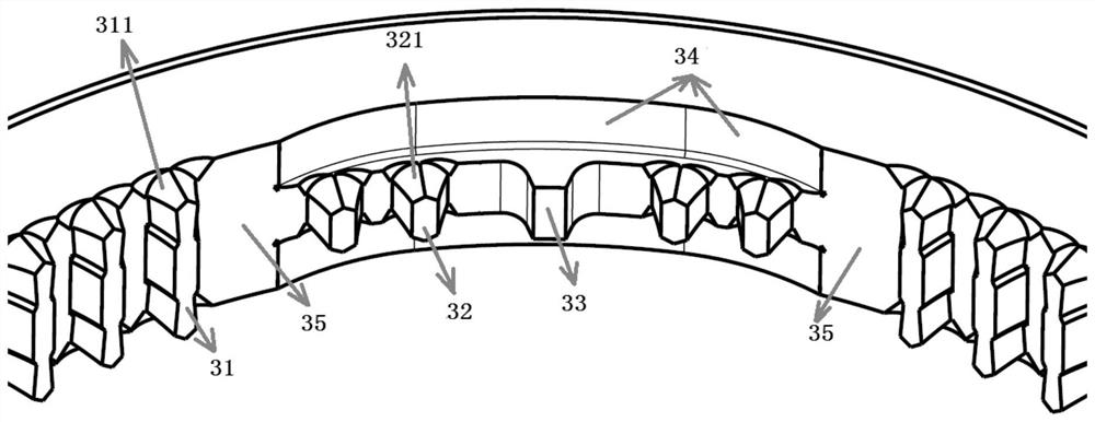
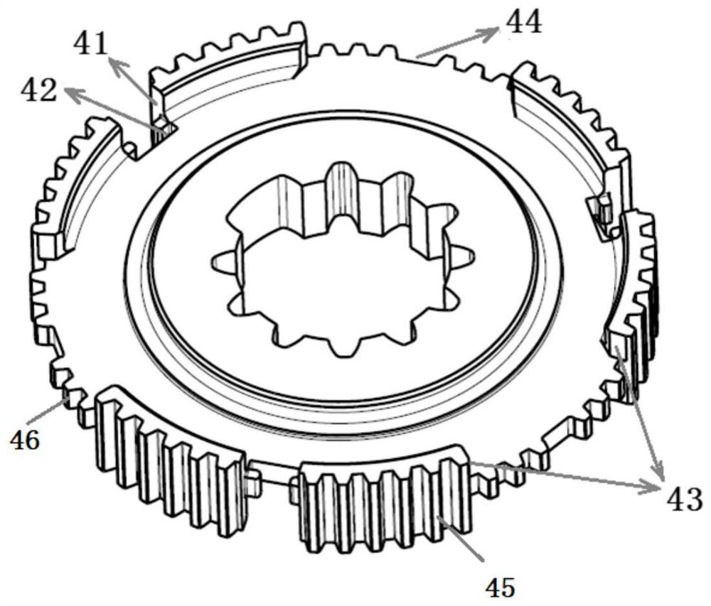
[0100]The embedded single-cone synchronizer includes a gear hub 4, a sliding gear sleeve 3, a steel ball spring packaged slider body 5 and a pair of locking rings 6; the sliding gear sleeve 3 is set on the outer circumference of the gear hub 4, And can axially slide relative to the gear hub 4; the steel ball spring packaged slider body 5 is arranged between the sliding gear sleeve 3 and the gear hub 4, and is located in the radial groove 42 of the gear hub 4 (such as Figure 4 ); a pair of locking rings 6 are respectively nested at both ends of the gear hub 4 .

[0101] In order to reduce the ins...

Embodiment 2

[0111] Such as Figure 9 As shown, the synchronizer of this embodiment is an embedded double-cone synchronizer, which is arranged between the first gear assembly 1 and the second gear assembly 2. The first gear assembly 1 is composed of the first gear 11 and the first gear assembly. The second gear assembly 2 is composed of the second gear 21 and the second combined ring gear 22 .

[0112] The embedded double-cone synchronizer includes gear hub 4, sliding gear sleeve 3, steel ball spring packaged slider body 5, a pair of locking rings 6, a pair of first friction rings 7 and a pair of second friction rings 8 ; The sliding gear sleeve 3 is set on the outer circumference of the gear hub 4, and can slide axially relative to the gear hub 4; the steel ball spring packaged slider body 5 is arranged between the sliding gear sleeve 1 and the gear hub 2, and Located in the radial groove of the gear hub 2; a pair of locking rings 6 are respectively nested at both ends of the gear hub 2;...

Embodiment 3

[0123] Such as Figure 15 As shown, the synchronizer of this embodiment is an embedded three-cone synchronizer. On the basis of the solution of Embodiment 1, a pair of first friction rings 7 and a pair of The second friction ring 8, at the same time in order to make the first friction ring 7 and the locking ring 6 can rotate synchronously, the corresponding structure of the locking ring 6 has been adjusted; Conical surface forms the first friction pair with the inner conical surface of the first annular boss 13 and the second annular boss 23 respectively, the inner conical surface of a pair of first friction rings 7 and the outer outer surface of a pair of second friction rings 8 respectively. The tapered surfaces form the second friction pair, and the inner tapered surfaces of a pair of second friction rings 8 respectively form the third friction pair with the outer tapered surfaces of a pair of locking rings 6; during the synchronization process, the first friction pair, the...


PUM


Abstract

The invention puts forward a high-capacity embedded conical-surface synchronizer and a transmission adopting the synchronizer so as to solve the technical problems that gears of high-torque transmissions are relatively short in lift and users require easier and more convenient gear shifting. According to the synchronizer and the transmission, a circular boss with the inner wall being a conical surface is arranged on a gear assembly, and an outer friction ring of the synchronizer is embedded in the circular boss, so that the axial mounting distance of the synchronizer is reduced, the width of agear can be increased under the condition that the total length of the transmission is not increased, and the bending fatigue and contact fatigue life of the gear is prolonged; a locking ring is embedded in a gear hub, and the axial size of the synchronizer is further reduced, so that the gear engagement stroke of a sliding gear sleeve is reduced, the length of a rocker arm of the transmission can be allowed to be increased under the condition that the gear engagement stroke of a cab is unchanged, the large lever ratio can be realized, the gear shifting ability of the synchronizer is improved, the gear engagement force and the idling force of a driver are reduced, and gear engagement is easier and more convenient.

Description

technical field [0001] The invention relates to a large-capacity embedded cone synchronizer and a transmission. Background technique [0002] With the development of high-horsepower and high-torque manual transmissions, it has become extremely difficult for traditional synchronizers to achieve smaller transmission lengths through smaller installation distances and shift strokes, or to reduce the installation of synchronizers when the length of the transmission remains the same. It is also difficult to implement measures to increase the gear width by increasing the pitch to increase the bending fatigue and contact fatigue life of the gear. [0003] In addition, users have higher and higher requirements for the convenience of shifting, and drivers require lighter shifting force and shifting force, no impact and frustration during the shifting process, and reduced driving labor intensity. Contents of the invention [0004] In order to solve the technical problems of low gear...

Claims


Application Information

Patent Timeline
Patent Type & Authority Applications(China)
IPC IPC(8): F16D23/02F16D23/06F16D13/74F16H61/04F16H3/12
CPCF16D23/025F16D23/06F16D13/74F16H61/0403F16H3/12F16D2023/0625F16D2023/0656F16D2023/0631F16D2023/0618
Inventor 魏小强张发勇彭立印张海涛田晨高建敏李泽汪鹏鹏
Owner SHAANXI FAST AUTO DRIVE GROUP CO LTD
Learn More