Slurry mixing device for non-woven fabric production

A technology of mixing devices and non-woven fabrics, which is applied to mixers, mixers with rotating stirring devices, transportation and packaging, etc., which can solve the problems of serious heat loss and inconvenient cleaning of the inner cavity

Inactive Publication Date: 2020-10-23
泗县玖知和科技信息咨询有限公司
0 Cites 0 Cited by

AI-Extracted Technical Summary

Problems solved by technology

[0003] The heat loss of the existing non-woven raw material mixing equipment is relatively...

Method used

[0020] Further, a buffer pad 13 is provided at the bottom position between the inner ba...

Abstract

The invention relates to the technical field of non-woven fabric raw material production mixing equipment, in particular to a slurry mixing device for non-woven fabric production. The slurry mixing device comprises an inner barrel body, an outer barrel body and a top cover, a motor is arranged above the top cover; one end of a motor output shaft is connected with a stirring rod through a coupler;the stirring rod penetrates through the top cover and extends into an inner cavity of the inner barrel body; stirring teeth are arranged on the outer wall of the stirring rod; a fixed seat is arrangedon the outer wall of the outer barrel body; an electric telescopic rod is arranged at the upper part of the fixed seat; one end of the bottom of the electric telescopic rod is fixedly connected withthe fixed seat, and one end of the top is fixedly connected with the top cover; a heat insulation sealing ring is arranged on the upper portion between the inner barrel body and the outer barrel body,a heating device is arranged in the middle of the space between the inner barrel body and the outer barrel body, a discharging pipe is arranged at the bottom of the outer barrel body, one end of thetop of the discharging pipe is communicated with an inner cavity of the inner barrel body, the heat utilization rate can be increased, electric energy losses are reduced, and meanwhile the inner cavity is convenient to wash and clean.

Application Domain

Rotary stirring mixersTransportation and packaging +2

Technology Topic

Woven fabricEngineering +5

Image

  • Slurry mixing device for non-woven fabric production

Examples

  • Experimental program(1)

Example Embodiment

[0018] The technical solutions in the embodiments of the present invention will be clearly and completely described below with reference to the accompanying drawings in the embodiments of the present invention. Obviously, the described embodiments are only a part of the embodiments of the present invention, but not all of the embodiments. Based on the embodiments of the present invention, all other embodiments obtained by those of ordinary skill in the art without creative efforts shall fall within the protection scope of the present invention.
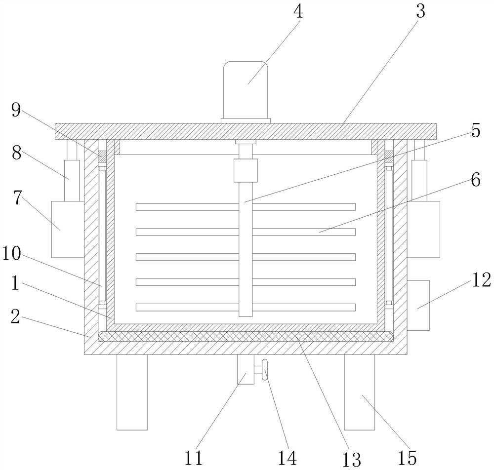
[0019] like figure 1 As shown, the slurry mixing device for non-woven fabric production in this embodiment includes an inner barrel 1, an outer barrel 2 and a top cover 3. A motor 4 is provided at the upper position of the top cover 3, and one end of the output shaft of the motor 4 passes through a coupling. A stirring rod 5 is connected, the stirring rod 5 extends through the top cover 3 to the inner cavity of the inner barrel 1, the stirring teeth 6 are arranged on the outer wall of the stirring rod 5, the fixing seat 7 is arranged on the outer wall of the outer barrel 2, and the upper position of the fixing seat 7 is arranged There is an electric telescopic rod 8, one end of the bottom of the electric telescopic rod 8 is fixedly connected with the fixed seat 7, and one end of the top is fixedly connected with the top cover 3, the upper part between the inner barrel 1 and the outer barrel 2 is provided with a heat insulation sealing ring 9, the inner barrel 1 and the outer barrel 2 is provided with a heating device 10 in the middle, and a discharge pipe 11 is provided at the bottom of the outer barrel 2. One end of the top of the discharge pipe 11 is communicated with the inner cavity of the inner barrel 1, and the outer wall of the outer barrel 2 is also located. A controller 12 is provided. The design of the inner and outer barrels can increase heat preservation and reduce heat loss, thereby reducing the loss of electric energy. The heat insulation sealing ring 9 at the upper position between the inner barrel 1 and the outer barrel 2 can lock the heat and further reduce the heat loss. , when the inner wall of the inner barrel 1 needs to be cleaned, the electric telescopic rod 8 is activated by the controller 12 to raise the top cover 3, and then the inner wall of the inner barrel 1 is rinsed with high-pressure water and a brush, so that the inner wall of the inner barrel 1 can be washed clean , to avoid agglomeration of the remaining material on the wall of the inner barrel.
[0020] Further, a buffer pad 13 is provided at the bottom position between the inner barrel 1 and the outer barrel 2 . Cushioning pads reduce vibrations during mixing.
[0021] Further, four fixed seats 7 are provided at equal angles at the position of the outer wall of the outer barrel 2 .
[0022] Further, the discharge pipe 11 is also provided with an on-off valve 14 .
[0023] Further, a support leg 15 is provided at the bottom position of the outer tub body 2 .
[0024] Working principle: In practical application, the outer barrel 2 can use a thermal insulation barrel to increase the thermal insulation effect. The electric telescopic rod 8 is activated by the controller 12 to raise the top cover 3, and then the raw materials that need to be mixed are injected into the inner barrel 1, and then passed through. The controller 12 resets the top cover 3. After the reset is completed, the controller 12 starts the heating device 10 to heat the inner barrel 1. The heat insulation sealing ring 9 at the upper position between the body 1 and the outer barrel body 2 can lock the heat and further reduce the loss of heat), and then start the motor 4 through the controller 12, and the motor 4 drives the stirring rod 5 to rotate, thereby driving the stirring teeth. 6. Stir and mix the raw materials in the inner cavity of the inner barrel 1. After mixing, turn off the motor through the controller 12, open the switch valve 14, and discharge the material through the discharge pipe 11. When the inner wall of the inner barrel 1 needs to be cleaned, control the The device 12 activates the electric telescopic rod 8 to lift the top cover 3, and then uses high-pressure water to the inner wall of the inner barrel 1 and cooperates with the brush to rinse the inner wall of the inner barrel 1 to avoid the remaining materials from caking on the inner wall of the inner barrel 1.

PUM

no PUM

Description & Claims & Application Information

We can also present the details of the Description, Claims and Application information to help users get a comprehensive understanding of the technical details of the patent, such as background art, summary of invention, brief description of drawings, description of embodiments, and other original content. On the other hand, users can also determine the specific scope of protection of the technology through the list of claims; as well as understand the changes in the life cycle of the technology with the presentation of the patent timeline. Login to view more.
Why Eureka
Try Eureka