
High-precision distributed temperature measurement system

A distributed, high-precision technology, applied in thermometers, measuring devices, measuring heat, etc., can solve problems such as long distances of temperature acquisition circuits, large mutual noise interference, and thermoelectric potential errors

Inactive Publication Date: 2020-10-23
BEIJING INST OF SPACECRAFT SYST ENG
View PDF7 Cites 0 Cited by
  • Summary
  • Abstract
  • Description
  • Claims
  • Application Information

AI Technical Summary

Problems solved by technology

[0006] (1) The temperature controller used in aerospace is arranged in the cabin, and its operating temperature is relatively wide, generally -15°C to +50°C, resulting in a large temperature drift of the system, which is mainly reflected in the reference resistor, amplifier, reference voltage source, constant Temperature drift of current source, AD and other devices
[0007] (2) The temperature sensor is far away from the temperature acquisition circuit located inside the temperature controller, which may require cable transfer, and there is contact resistance
[0008] (3) Long-distance transmission of weak measurement signals (microvolt-level voltage signals), susceptible to electromagnetic interference from the surrounding environment inside and outside the satellite cabin
[0009] (4) The temperature acquisition circuit and the heating drive circuit are all arranged inside the temperature controller, and the mutual noise interference is large
[0010] (5) In the field of high-precision temperature measurement, due to the difference in the thermal environment between the temperature measurement object and the temperature measurement line, the error caused by the thermoelectric potential cannot be ignored
In order to eliminate this effect, the existing technology measures the voltage across the thermal resistance from two directions (i.e. the positive and negative of the excitation current) and calculates the average value, which eliminates the influence of thermal electric potential and increases the complexity of the measurement circuit.

Method used


Image

  • High-precision distributed temperature measurement system
  • High-precision distributed temperature measurement system
  • High-precision distributed temperature measurement system

Examples


Embodiment Construction

[0027] The present invention will be described in detail below with reference to the accompanying drawings and examples.

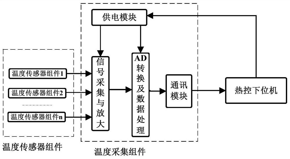
[0028] This embodiment provides a high-precision distributed temperature measurement system, such as image 3 As shown, the temperature measurement system includes a temperature sensor component, a temperature acquisition component and a thermal control slave computer. The temperature sensor component is used for temperature sensing; the temperature acquisition component is used to measure the resistance value of the temperature sensor component, and complete the quantization of the digital quantity, and transmit the digital quantity to the thermal control lower computer through the bus; the thermal control lower computer provides 5V, Secondary power supply such as 12V, in addition, it can also have temperature control function.

[0029] The temperature sensor assembly consists of a platinum resistance R t , Precision resistor R REF , signal conditionin...


PUM


Abstract

The invention discloses a high-precision distributed temperature measurement system, which comprises a temperature sensor assembly, a temperature acquisition assembly and a thermal control lower computer, wherein the temperature sensor assembly comprises a platinum resistor, a precision resistor, a signal conditioning circuit and a packaging shell body; the platinum resistor and the precision resistor are connected in series and installed in the packaging shell body; the platinum resistor and the precision resistor are temperature quantity signal input sources, and the conditioning circuit conditions a temperature measured signal into a voltage signal to be acquired by the temperature acquisition assembly; the temperature sensor assembly and the temperature acquisition assembly are arranged at temperature control objects, the number of the temperature acquisition assemblies is one, and one temperature acquisition assembly corresponds to 1-4 temperature sensor assemblies; and a multi-way switch is used for switching different temperature acquisition assemblies, the potential difference between the platinum resistor and the precision resistor is acquired, the potential difference isamplified and converted into a digital signal, the digital signal is transmitted to the thermal control lower computer, and the measured temperature is obtained through calculation by means of the thermal control lower computer. According to the high-precision distributed temperature measurement system, the temperature measurement precision and stability are effectively improved.

Description

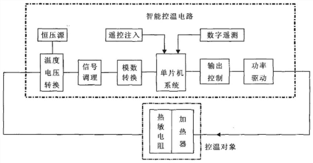
technical field [0001] The invention relates to the technical field of spacecraft temperature measurement and control, in particular to a high-precision distributed temperature measurement system. Background technique [0002] Electric heating active thermal control devices generally include heaters, controllers and temperature sensors, forming a closed-loop control loop, such as figure 1 shown. The temperature sensor is used to obtain the temperature signal T of the controlled object m ; The heater provides heat as a control actuator. The controller will obtain the temperature signal with the set value T d Compare, so as to obtain the error signal e(k)=T d -T m , and combined with the temperature control algorithm, generate the control output u to control the working state of the heater. [0003] The controller is the temperature controller, which is mainly responsible for temperature acquisition and control. The spacecraft temperature controller adopting the centrali...

Claims


Application Information

Patent Timeline
IPC IPC(8): G01K7/21G01K1/20
CPCG01K1/20G01K7/21
Inventor 童叶龙赵欣李一凡周宇鹏
Owner BEIJING INST OF SPACECRAFT SYST ENG
Learn More