Long-wave carbon dioxide laser isolation device

A carbon dioxide and laser isolation technology, applied to lasers, laser components, laser components, etc., can solve problems such as limited structure, poor flexibility, and beam distortion

Inactive Publication Date: 2020-10-23
CHANGCHUN INST OF OPTICS FINE MECHANICS & PHYSICS CHINESE ACAD OF SCI
View PDF10 Cites 3 Cited by
  • Summary
  • Abstract
  • Description
  • Claims
  • Application Information

AI Technical Summary

Problems solved by technology

[0005] In order to solve the above problems, the present invention provides a long-wave carbon dioxide laser isolation device, which can solve the problems of beam distortion, complex adjustment, limited structure and poor flexibility caused by the existing saturated gas absorption isolation device, which is more flexible and concise and has higher isolation efficiency

Method used


Image

  • Long-wave carbon dioxide laser isolation device

Examples


Embodiment Construction

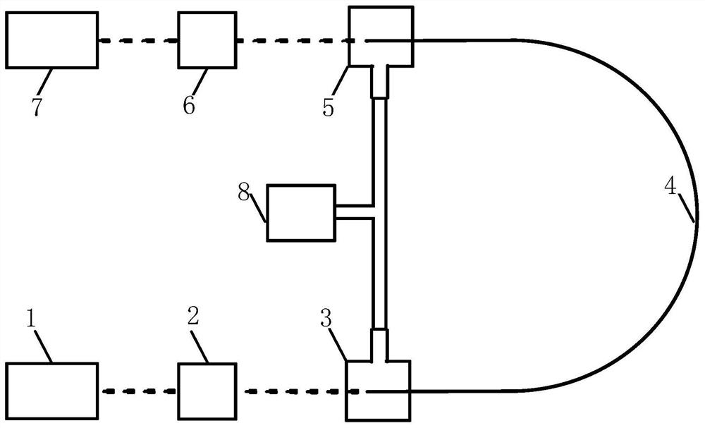
[0019] The core of the present invention is to provide a long-wave carbon dioxide laser isolation device, which can solve the problems of beam distortion, complex adjustment, limited structure and poor flexibility caused by the existing saturated gas absorption isolation device, which is more flexible and concise and has higher isolation efficiency.

[0020] The following will clearly and completely describe the technical solutions in the embodiments of the present invention with reference to the accompanying drawings in the embodiments of the present invention. Obviously, the described embodiments are only some, not all, embodiments of the present invention. Based on the embodiments of the present invention, all other embodiments obtained by persons of ordinary skill in the art without making creative efforts belong to the protection scope of the present invention.

[0021] An embodiment of a long-wave carbon dioxide laser isolation device provided by the present invention is ...


PUM

PropertyMeasurementUnit
diameteraaaaaaaaaa

Abstract

The invention discloses a long-wave carbon dioxide laser isolation device. The device is arranged between a seed laser and a laser amplifier. The device comprises a beam shrinking lens group connectedwith the seed laser, the other end of the beam shrinking lens group is connected with a first sealing window of a hollow-core optical fiber, the other end of the hollow-core optical fiber is providedwith a second sealing window, the second sealing window is further connected with the laser amplifier through a beam expander set, and the hollow-core optical fiber is filled with a gas with the saturated absorption characteristic and is used for allowing laser transmitted in the forward direction to penetrate through and absorbing laser transmitted in the reverse direction. The long-wave carbondioxide laser isolation device can solve the problems that an existing saturated gas absorption isolation device causes light beam distortion, is complex in adjustment, limited in structure and poor in flexibility, and is more flexible, simpler and higher in isolation efficiency.

Description

technical field [0001] The application belongs to the technical field of extreme ultraviolet lithography light sources, and in particular relates to a long-wave carbon dioxide laser isolation device. Background technique [0002] Photolithography technology is the core of modern large-scale integrated circuit manufacturing technology. Projection lithography technology using extreme ultraviolet light with a wavelength of 13.5nm is the mainstream technical approach of lithography technology at present. The realization methods include but are not limited to 10.6 μm carbon dioxide laser irradiation droplet tin target to generate plasma and then radiate 13.5nm extreme ultraviolet light. This method has the advantages of high conversion efficiency and less debris generation, and is currently a relatively mature 13.5nm extreme ultraviolet light Generate technical solutions. [0003] Laser-induced plasma radiating extreme ultraviolet light requires driving a carbon dioxide laser to...

Claims


Application Information

Patent Timeline
Patent Type & Authority Applications(China)
IPC IPC(8): H01S3/03H01S3/067H01S3/10
CPCH01S3/0315H01S3/06708H01S3/10
Inventor 孙俊杰郭劲陈飞潘其坤张阔于德洋张鲁薇何洋
Owner CHANGCHUN INST OF OPTICS FINE MECHANICS & PHYSICS CHINESE ACAD OF SCI
Why Eureka
Try Eureka