Long-tail H-bridge drive circuit of brush motor

A bridge drive circuit, brushed motor technology, applied in the direction of DC motor rotation control, excitation or armature current control, DC motor speed/torque control, etc., can solve the problem of low maximum applicable voltage, large static resistance, low-speed starting torque And other issues

Pending Publication Date: 2020-10-23
南京长亚轨道交通科技有限公司
View PDF0 Cites 0 Cited by
  • Summary
  • Abstract
  • Description
  • Claims
  • Application Information

AI Technical Summary

Problems solved by technology

[0002] The railway passenger car manufacturing industry has developed by leaps and bounds in recent years. A large number of automation equipment are used in various functional units of the vehicle, among which rotating motors are usually used as actuators. At present, the commonly used motor forms for vehicles include DC brushless motors and DC brushed motors. In addition to its own significant advantages, brushless motors often rely on the driver and internal software. The drive logic is relatively complex, and problems such as software runaway and hardware damage are prone to occur; and the problems of low-speed performance and small starting torque are in the The non-inductive brushless motor is particularly prominent; because many equipment on the vehicle, such as the wiper drive motor, coupler motor, and automatic door motor, have very large static resistance, which often causes problems in starting the brushless motor when it is running. Therefore, the above important equipment The driving motors used are almost all brushed DC motors, and their excellent mechanical characteristics and simple and reliable driving and speed regulation methods can well meet the needs of railway vehicle working conditions
[0003] In the field of DC brushed motor drive, when there is a need for speed regulation in the application, almost all H-bridge drive circuits composed of MOSFET field effect transistors are used; existing designs are driven by dedicated H-bridge drive chips or discrete components, such as IR2110 and other dedicated H-bridge driver chip, the drive of its upper tube depends on the bootstrap voltage established by the alternate conduction of the upper and lower tubes to realize the drive of the upper tube; some dedicated modules adopt the form of a built-in charge pump to realize the drive of the upper tube However, the built-in charge pump module must have a built-in H-bridge or a half-arm H-bridge, and its maximum applicable voltage is low, which is far from meeting the maximum voltage requirement of DC145V for the driving motor of railway passenger car equipment; At least two PWM signals or four PWM signals with a phase difference of 180 degrees are required, and a 2-5% duty cycle must be reserved in each driving pulse cycle to drive the lower tube to be turned on to achieve To establish the bootstrap voltage required for driving the upper tube, in order to ensure that the two tubes will not be turned on at the same time during the alternate conduction process of driving the upper and lower tubes, it is also necessary to leave a certain width of dead zone on the driving signals of the upper and lower tubes Time, multi-channel PWM signals with complex phase and timing relationships lead to complex design and debugging, which seriously reduces the reliability of the system, which is contrary to the purpose of the first reliability of railway passenger car equipment

Method used


Image

  • Long-tail H-bridge drive circuit of brush motor

Examples


Embodiment Construction

[0021] The present invention will be described in detail below in conjunction with the accompanying drawings and embodiments.

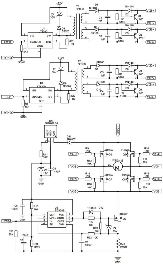
[0022] Such as figure 1 Shown: This embodiment is a long-tailed H-bridge driving circuit for a brushed motor, including an H-shaped commutating bridge circuit, a field-effect transistor gate drive power supply circuit, a long-tailed PWM widening circuit and a high-voltage constant-current stabilizer Voltage power supply circuit; FET grid drive power circuit provides driving power for H-shaped commutation bridge circuit, long-tail PWM width adjustment circuit is connected in series with H-shaped commutation bridge circuit, high-voltage constant current regulated power supply circuit Powers the long-tail PWM widening circuit.

[0023] In this embodiment, the FET grid drive power circuit includes a motor reverse control isolated drive power circuit and a motor forward control isolated drive power circuit; a motor reverse control isolated drive power circu...


PUM


Abstract

The invention discloses a long-tail type H-bridge driving circuit of a brush motor. The long-tail type H-bridge driving circuit comprises an H-shaped reversing bridge circuit, a field effect transistor grid driving power supply circuit, a long-tail type PWM width modulation circuit and a high-voltage constant-current voltage-stabilizing power supply circuit, wherein the field effect transistor grid driving power supply circuit provides a driving power supply for the H-shaped reversing bridge circuit, the long-tail type PWM width modulation circuit is connected with the H-shaped reversing bridge circuit in series, and the high-voltage constant-current voltage-stabilizing power supply circuit supplies power to the long-tail type PWM width modulation circuit. According to the long-tail type H-bridge driving circuit, the circuit design is simplified, and the overall reliability of the circuit is essentially improved; and 100% duty ratio speed regulation can be realized, only one path of required driving and speed regulation PWM signal is needed, and the situation of tube explosion caused by simultaneous conduction of upper and lower tubes of an H bridge due to problems of a phase and time sequence generation circuit or software of multiple paths of PWM signal waves is completely avoided.

Description

technical field [0001] The invention relates to a brush motor drive circuit related to a railway passenger car, a locomotive wiper drive motor, a coupler motor and an automatic door motor, in particular to a brush motor long-tail H-bridge drive circuit, which belongs to the technical field of motors and railway passenger cars field of manufacturing technology. Background technique [0002] The railway passenger car manufacturing industry has developed by leaps and bounds in recent years. A large number of automation equipment are used in various functional units of the vehicle, among which rotating motors are usually used as actuators. At present, the commonly used motor forms for vehicles include DC brushless motors and DC brushed motors. In addition to its own significant advantages, brushless motors often rely on the driver and internal software. The drive logic is relatively complex, and problems such as software runaway and hardware damage are prone to occur; and the pr...

Claims


Application Information

Patent Timeline
Patent Type & Authority Applications(China)
IPC IPC(8): H02P7/03H02P7/29
CPCH02P7/04H02P7/05H02P7/295
Inventor 陈维忠许中荣
Owner 南京长亚轨道交通科技有限公司
Why Eureka
Try Eureka