
Textile plant dye extraction device

An extraction device and a technology for plant dyes, applied in the field of plant dye extraction devices for textiles, can solve problems such as plant waste, pigment extraction, and inability to meet people's needs for use.

Active Publication Date: 2020-10-27
哈尔滨市七彩莲花文化艺术发展有限公司
View PDF6 Cites 2 Cited by
  • Summary
  • Abstract
  • Description
  • Claims
  • Application Information

AI Technical Summary

Problems solved by technology

[0004] The design and structure of the dye extraction device in the above-mentioned patent is simple, and it is impossible to extract most of the pigments in the plants, resulting in poor extraction quality of the pigments, which is easy to cause waste of plants, and obviously cannot meet the needs of people.

Method used


Image

  • Textile plant dye extraction device
  • Textile plant dye extraction device
  • Textile plant dye extraction device

Examples


Embodiment 1

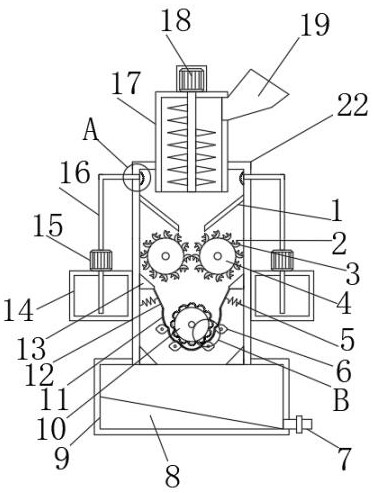
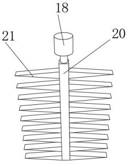
[0029] refer to Figure 1-5 , a plant dye extraction device for textiles, comprising a working box 22, the top outer wall of the working box 22 is provided with a feeding port, and the inner wall of the feeding port is inserted with a crushing box 17, and the top outer wall of the crushing box 17 is fixed by screws. Motor 18, and the output shaft of motor 18 is connected with rotating rod 20 by shaft coupling, and the outer wall of rotating rod 20 is fixed with the pulverizer 21 of equidistant distribution by screw, and one side outer wall of working box 22 is fixed with rotary motor by screw, and The output shaft of the rotating motor is connected with a crushing roller 4 through a coupling, and the outer wall of the crushing roller 4 is fixed with crescent-shaped crushing knives 3 distributed in an equidistant ring by screws, and the outer wall of the crescent-shaped pulverizing knife 3 is welded with crushing teeth 2. The inner walls of both sides of the box 22 are fixed wi...

Embodiment 2

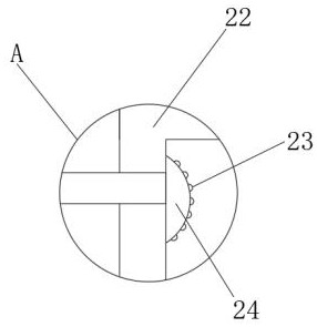
[0038] refer to figure 1 , a plant dye extraction device for textiles. Compared with Embodiment 1, this embodiment also includes that the outer walls of both sides of the working box 22 are fixed with water tanks 14 by screws, and the top outer walls of the water tank 14 are fixed with water pumps 15 by screws. The output end of the water pump 15 is socketed with a water pipe 16, and the end of the water pipe 16 away from the water pump 15 is socketed with a spray block 24. The outer wall of the spray block 24 is provided with spray holes distributed equidistantly, and the inner wall of the spray hole is inserted with an atomizer. Nozzle 23.

[0039] The water pump 15 can pump water from the water tank 14 and enter the working box 22 through the atomizing nozzle 23. On the one hand, the clean water can wash away the slag bonded to the crushing roller 4, and on the other hand, it can soak the slag in the filter cloth 11. , which can make it easier for the plant pigment to be e...


PUM


Abstract

The invention belongs to the technical field of textile production, in particular to a textile plant dye extraction device. Directed at the problems that the existing dye extraction device is simple in design structure, cannot extract most of pigments in plants, so that the pigment extraction quality is poor and plants are easily wasted, the invention provides the following scheme that: the devicecomprises a working box, a feeding hole is formed in the outer wall of the top of the working box, a crushing box is inserted into the inner wall of the feeding hole, and a motor is fixed on the outer wall of the top of the crushing box through screws. According to the invention, when cams rotate, under the extrusion action of the cams, bulges and convex particles, juice in plant crushed materials is squeezed out and can fall into a recovery box along filter cloth after being squeezed out, and crushed residues can be left in the filter cloth, so that a good dye extraction effect is achieved,most of pigments in plants can be extracted, the pigment extraction quality is good, and plant waste is not likely to be caused.

Description

technical field [0001] The invention relates to the technical field of textile production, in particular to a plant dye extraction device for textile. Background technique [0002] The original meaning of textile is taken from the general term of spinning and weaving, but with the continuous development and improvement of the textile knowledge system and subject system, especially after the emergence of non-woven textile materials and three-dimensional composite weaving technologies, it is not only the traditional hand spinning And weaving, also including non-woven technology, modern three-dimensional weaving technology, modern electrostatic nano-netting technology and other clothing, industrial and decorative textiles. Therefore, modern textile refers to a variety of fibers or fiber aggregates. Scale structure processing technology often needs to extract dyes from plants in the process of textile production. [0003] After retrieval, the Chinese patent authorization number...

Claims


Application Information

Patent Timeline
Patent Type & Authority Applications(China)
IPC IPC(8): C09B61/00C09B67/54B02C18/10B02C18/14B02C18/18B02C18/22B02C23/20B08B3/02B30B9/20B30B15/00
CPCC09B61/00C09B67/0096B02C18/10B02C18/14B02C18/18B02C18/2291B02C23/20B08B3/02B30B9/20B30B15/00Y02W30/66
Inventor 安丽
Owner 哈尔滨市七彩莲花文化艺术发展有限公司
Learn More