Small-size optical detector

A light detector and small-size technology, applied in the field of light detection, can solve the problems of large size, low resolution, and inability to meet the needs of light detection in narrow spaces, and achieve small size, high light detection sensitivity, and good resolution. Effect

Inactive Publication Date: 2020-10-30
中山科立特光电科技有限公司
View PDF0 Cites 0 Cited by
  • Summary
  • Abstract
  • Description
  • Claims
  • Application Information

AI Technical Summary

Problems solved by technology

The size of traditional light detection equipment is large, which cannot meet the needs of light detection in narrow spaces, or the spatial resolution is low

Method used


Image

  • Small-size optical detector
  • Small-size optical detector

Examples


Embodiment 1

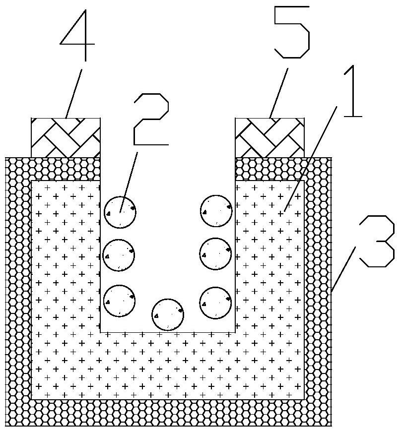
[0020] The invention provides a small-sized photodetector. Such as figure 1 As shown, the small-sized photodetector includes a pyroelectric material part 1 , micro-nano particles 2 , a graphene layer 3 , a source 4 , and a drain 5 . The thermoelectric material part 1 is barrel-shaped, that is to say, the thermoelectric material part 1 has a cavity inside, and the cavity has an opening on the top surface of the thermoelectric material part 1 . The material of the thermoelectric material part 1 is lead zirconate titanate, lithium tantalate, lithium niobate, gallium nitride, and cesium nitrate. The micro-nano particles 2 are arranged on the inner wall and the inner bottom surface of the thermoelectric material part 1 . The graphene layer 3 covers the outer wall and the top surface of the thermoelectric material part 1 , that is, the graphene layer 2 is coated on the side, bottom and top surfaces of the thermoelectric material part 1 . The source electrode 4 and the drain elect...

Embodiment 2

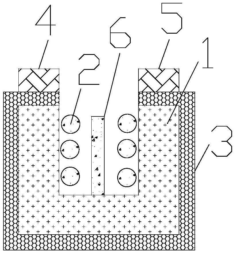
[0030] On the basis of Embodiment 1, a column 6 is further provided on the inner bottom surface of the thermoelectric material part, and the material of the column 6 is a noble metal or a medium with a high refractive index. At this time, the size of the thermoelectric material part 1 is larger than that of the thermoelectric material part 1 in Embodiment 1, and the size of the interior of the thermoelectric material part 1 is larger than that of the thermoelectric material part 1 in Embodiment 1. The column 6 is arranged on the inner bottom surface of the thermoelectric material part 1, so as to generate coupling between the column 6 and the micro-nano particles 2, thereby generating more light absorption, thereby increasing the temperature difference between the inside and the outside of the thermoelectric material part 1, and more The conductive properties of the graphene layer 3 are changed in many ways to improve the sensitivity of light detection. This embodiment is suit...


PUM

PropertyMeasurementUnit
diameteraaaaaaaaaa
heightaaaaaaaaaa

Abstract

The invention relates to the field of optical detection, and particularly provides a small-size optical detector. A thermoelectric material part is barrel-shaped, micro-nano particles are arranged onthe inner wall and the inner bottom surface of the thermoelectric material part, a graphene layer coats the outer wall and the top surface of the thermoelectric material part, and a source electrode and a drain electrode are respectively arranged on the graphene layer on the top surface of the thermoelectric material part. During application, light to be measured irradiates the thermoelectric material part, is coupled into the thermoelectric material part, then is absorbed by the micro-nano particles and is converted into heat, and the temperature difference between the interior and the exterior of the thermoelectric material part causes lattice structure polarization, so that the thermoelectric material part generates a local electric field; the electric field changes the conductive characteristic of the graphene layer, and optical detection is realized according to change of the conductive characteristic of the graphene layer. According to the invention, the size of the thermoelectric material part is small, and small-space optical detection can be realized. In addition, the method has the advantages of high sensitivity and high spatial resolution.

Description

technical field [0001] The invention relates to the field of light detection, in particular to a small-sized light detector. Background technique [0002] Optical detection technology involves several important frontier fields and occupies an important position in the national economy. The size of traditional light detection equipment is large, which cannot meet the needs of light detection in narrow spaces, or has low spatial resolution. Contents of the invention [0003] In order to solve the above problems, the present invention provides a small-sized photodetector, comprising: a thermoelectric material part, micro-nano particles, a graphene layer, a source electrode, and a drain electrode; the thermoelectric material part is barrel-shaped, and the micro-nano particles are arranged on On the inner wall and inner bottom surface of the material part, the graphene layer covers the outer wall and top surface of the thermoelectric material part, and the source and drain ele...

Claims


Application Information

Patent Timeline
Patent Type & Authority Applications(China)
IPC IPC(8): G01J1/42H01L35/22
CPCG01J1/42H10N10/855
Inventor 不公告发明人
Owner 中山科立特光电科技有限公司
Why Eureka
Try Eureka