Scanner and coaxial and non-coaxial radar systems using same

A technology for scanners and balanced detectors, which is applied in the field of coaxial and non-coaxial radar systems, can solve the problems of low resolution, high price of Mems, and large volume, so as to improve detection accuracy, facilitate cost reduction and mass production, and improve The effect of detection distance

Active Publication Date: 2020-10-30
HANGZHOU XIGHT SEMICON CO LTD
View PDF16 Cites 4 Cited by
  • Summary
  • Abstract
  • Description
  • Claims
  • Application Information

AI Technical Summary

Problems solved by technology

[0003] The current laser radar includes mechanical scanning laser radar, Flash laser radar, Mems scanning laser radar and OPA radar. The traditional mechanical laser radar uses a mechanical device to rotate and scan to obtain 360-degree point cloud information and construct a complete three-dimensional image. However, due to the slow mechanical scanning speed and low resolution, the obtained 3D image cannot completely present small objects. Secondly, the mechanical scanning l

Method used


Image

  • Scanner and coaxial and non-coaxial radar systems using same
  • Scanner and coaxial and non-coaxial radar systems using same
  • Scanner and coaxial and non-coaxial radar systems using same

Examples


Embodiment 1

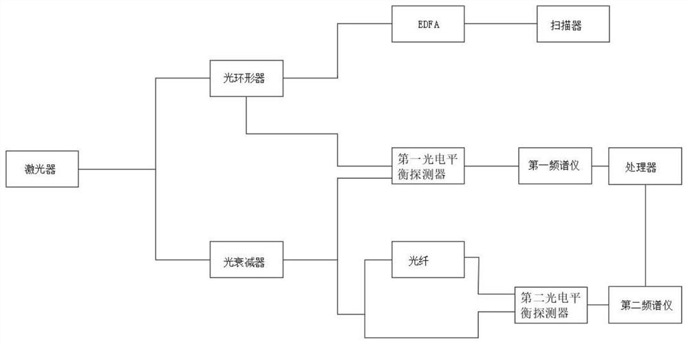
[0043] Such as figure 2 As shown, a coaxial laser radar system is integrated by connecting working parts with multiple splitters: the specific connection method is as follows:

[0044] The laser is used to emit laser light, output an optical signal, and transmit the optical signal to the optical circulator and the optical attenuator respectively through the first splitter to obtain the first optical signal and the local optical signal;

[0045] An optical circulator is used to realize bidirectional communication of optical signals; in this embodiment, the optical circulator has 3 interfaces, wherein the first interface is connected to the first splitter, the second interface is connected to an optical amplifier, and the third interface is connected to the optical amplifier. The interface is connected to the detection line to facilitate subsequent calculation of the scanning distance;

[0046] an optical amplifier, configured to receive the optical signal transmitted by the f...

Embodiment 2

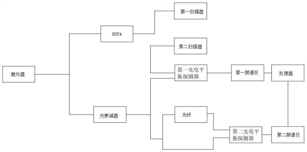
[0053] Such as image 3 As shown, a non-coaxial lidar system is integrated by connecting working parts with multiple splitters:

[0054] The laser is used to emit laser light, output an optical signal, obtain a third optical signal and a local optical signal through the first splitter, and send the third optical signal and the local optical signal to the optical amplifier and the optical attenuator respectively;

[0055] The optical amplifier is used to receive the third optical signal, amplify it, and then send it to the scanner; wherein, noise removal and power enhancement are performed through the optical amplifier and the grating antenna group in the scanner to increase the measurement distance, Reduce external interference;

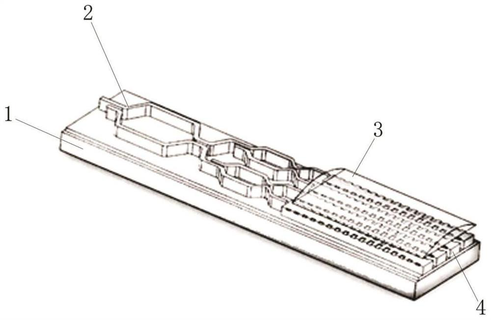
[0056] a first scanner, configured to output a third optical signal to free space;

[0057] The second scanner is configured to receive an optical signal in free space to obtain a fourth optical signal;

[0058] Optical attenuator, which receives ...


PUM


Abstract

A scanner and coaxial and non-coaxial radar systems using the same belong to the technical field of laser radars, and the scanner comprises a wafer substrate, a plurality of optical switches and a plurality of grating antenna groups; the plurality of optical switches and the plurality of grating antenna groups are fixedly arranged on the upper end surface of the wafer substrate; the plurality of optical switches are in one-to-one correspondence with the plurality of grating antenna groups. Namely, one grating antenna group is electrically connected with one optical switch. The plurality of grating antenna groups are distributed in an array to form a grating part; a lens module is movably arranged on the upper side of the grating part; secondly, two-dimensional scanning is carried out through the scanner; three-dimensional imaging is realized and the detection precision is improved by combining the distance information calculated by the system in the third dimension, noise is removed through joint participation of the optical amplifier and the grating antennas, the interference of the outside to a detection result is reduced, the detection distance is improved, and in addition, thesystem is integrated on the chip, the size is small, installation is simple and easy, and the cost reduction and the mass production are convenient.

Description

technical field [0001] The invention belongs to the technical field of laser radar, in particular to a scanner and a coaxial and non-coaxial radar system using the scanner. Background technique [0002] LiDAR is a sensor that uses laser light to detect and measure distances. Its principle is that the transmitting device emits laser light to the target, and the receiving device measures the delay and intensity of the returning laser light to measure the distance of the target. [0003] The current laser radar includes mechanical scanning laser radar, Flash laser radar, Mems scanning laser radar and OPA radar. The traditional mechanical laser radar uses a mechanical device to rotate and scan to obtain 360-degree point cloud information and construct a complete three-dimensional image. However, due to the slow mechanical scanning speed and low resolution, the obtained 3D image cannot completely present small objects. Secondly, the mechanical scanning laser radar is relatively ...

Claims


Application Information

Patent Timeline
IPC IPC(8): G01S17/08G01S17/89G01S7/481
CPCG01S17/08G01S17/89G01S7/4817G01S17/42G01S7/4816G01S17/931G01S7/4808G01S7/4812
Inventor 黄锦熙巩少斌
Owner HANGZHOU XIGHT SEMICON CO LTD
Why Eureka
Try Eureka