Lightweight design method for armor type thin-wall structure

A lightweight design and thin-walled structure technology, applied in design optimization/simulation, geometric CAD, special data processing applications, etc., can solve the problems affecting the overall weight and center of mass estimation of equipment, reduce structural weight, and low efficiency of ribs, etc. question

Active Publication Date: 2020-10-30
DALIAN UNIV OF TECH
View PDF4 Cites 2 Cited by
  • Summary
  • Abstract
  • Description
  • Claims
  • Application Information

AI Technical Summary

Problems solved by technology

Secondly, in order to adopt the chemical milling method, but the precision and controllability of this processing method are limited, the weight of the actual product obtained is often greater than the design weight, which will affect the estimation of the overall weight and center of mass of the equipment
The most accurate processing method is to use CNC machining to gradually mill out the reinforced thin-walled structure from a whole piece of material, but the processing process is very time-consuming and also greatly wastes materials
[0004] 2) The efficiency of some ribs is low
Since most of the ribs need to be arranged continuously, that is, they extend continuously from one end of the structure to the other end or connect end to end, which leads to the addition of material in areas that do not need to be added, thus failing to reduce the weight of the structure most effectively
[0005] 3) Under the combined thermal and mechanical load, high stress phenomenon is prone to occur
For this reason, in the process of heating up or cooling down, large stress concentration tends to occur at the root of the ribs, resulting in reduced structural life and even structural damage.

Method used


Image

  • Lightweight design method for armor type thin-wall structure
  • Lightweight design method for armor type thin-wall structure
  • Lightweight design method for armor type thin-wall structure

Examples


Embodiment Construction

[0037] In order to make the technical solutions and advantages of the present invention more clear, the technical solutions in the embodiments of the present invention are clearly and completely described below in conjunction with the drawings in the embodiments of the present invention:

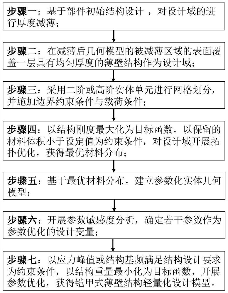
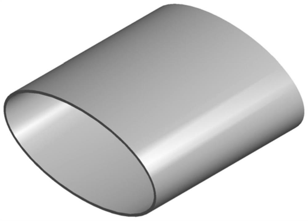
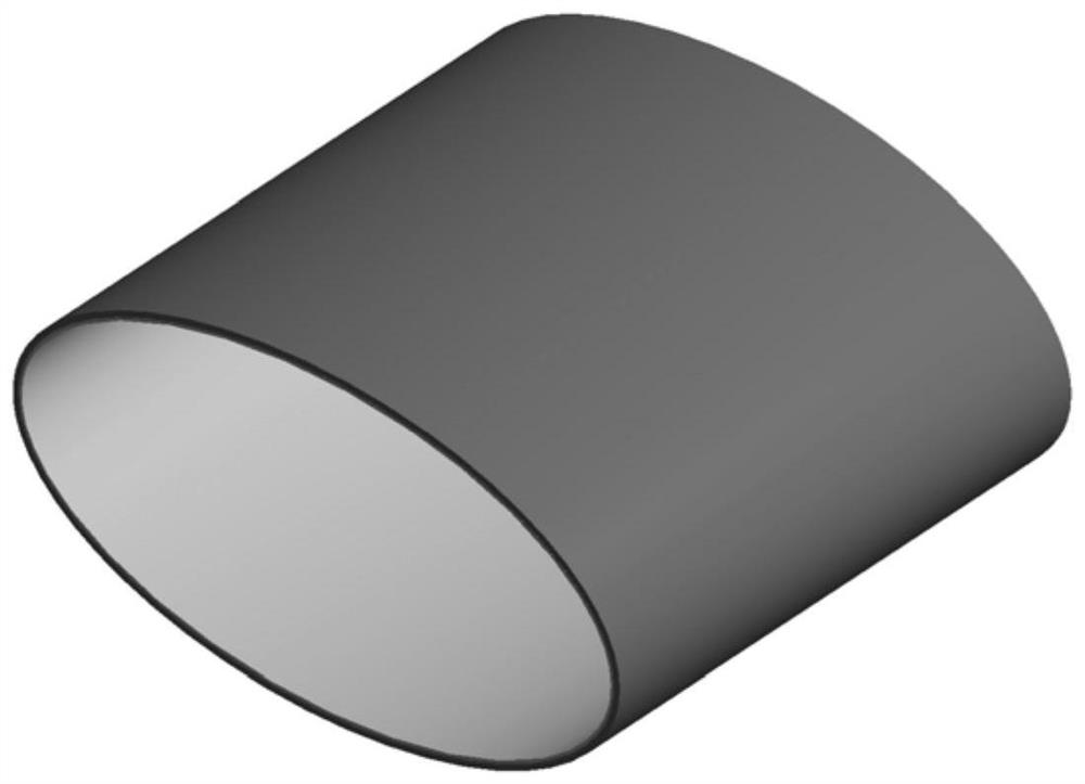
[0038] The characteristics of the armored thin-walled structure are as follows: (1) The designable thin-walled area in the armored thin-walled structure is composed of two areas with different thicknesses. The distribution and shape of the areas with different thicknesses are obtained by the corresponding optimization design process, which can be reasonably The mechanical properties of materials are used to effectively realize the lightweight structure; (2) The structural optimization design process has good integrity, covering the conceptual design stage and the detailed design stage, and both stages introduce applicable structural optimization design technology, so as to ensure that More ef...


PUM


Abstract

The invention discloses a lightweight design method for an armor type thin-wall structure, which belongs to the field of aerospace equipment and comprises the following steps: covering a layer of thin-wall structure with uniform thickness on the surface of a thinned area of a thinned geometric model on the basis of an initial structure design of an internal pressure part to obtain a geometric model to be optimized; performing mesh generation by adopting a second-order or high-order entity unit, and applying a boundary constraint condition and a load condition to obtain a finite element analysis model; obtaining optimal material distribution in a design domain; establishing a parameterized entity geometric model of the internal pressure component after topological optimization; and obtaining an optimal parameter optimization design variable value, and finally obtaining an armor type thin-wall structure lightweight design model of the design object component. The method completely comprises a conceptual design stage and a detailed design stage, meanwhile, a geometric model processing method required by topological optimization and a parameterized geometric model modeling method required by parameter optimization are provided, and the methods have good operability and convenience.

Description

technical field [0001] The invention relates to the field of aerospace equipment, in particular to a lightweight design method for an armored thin-walled structure. Background technique [0002] Thin-walled structures subject to internal pressure loads are widely used in aerospace, chemical machinery and many other engineering fields, such as pipelines, engine intakes, etc. In related fields, some equipment has higher requirements for lightweight structures. For a long time, the lightweight requirements of thin-walled structures have mostly been achieved by using reinforced design instead of uniform thickness design. This is because, under the same amount of material, the reinforced configuration has better bending resistance, so that the mechanical properties of the material can be effectively utilized. By introducing structural parameter optimization technology and optimizing the rib layout, the efficiency of material utilization can be further improved. However, no mat...

Claims


Application Information

Patent Timeline
Patent Type & Authority Applications(China)
IPC IPC(8): G06F30/10G06F30/23G06F111/04
CPCG06F30/10G06F30/23G06F2111/04
Inventor 阎琨蔡贤辉潘余程耿东孙国
Owner DALIAN UNIV OF TECH
Why Eureka
Try Eureka