Switching compensation system

A compensation system, switching technology, applied in the direction of AC network circuits, electrical components, circuit devices, etc., can solve the problems affecting the normal operation of the safe load of the power grid, the overloaded operation of lines and electrical equipment, and the failure of power consumption compensation to reach the expected value, etc. problems, to achieve stable and reliable data collection and processing, convenient monitoring, and increase stability.

Pending Publication Date: 2020-10-30
安徽交通职业技术学院
View PDF7 Cites 0 Cited by
  • Summary
  • Abstract
  • Description
  • Claims
  • Application Information

AI Technical Summary

Problems solved by technology

[0003] While studying the stability and safety of the power system, the operation mode of the power supply and the model selection of the electrical equipment will be considered, and a certain power consumption capacity will be set in advance. When the load runs continuously or is disturbed, the power loss will be too large , will lead to overload operation of lines and electrical equipment, affecting the safety of the power grid and the normal operation of the load
[0004] Usually, the fast switching compensation device is used to improve the load loss energy and make control decisions in terms of stabilizing the supply voltage and power factor. However, in the process of some parameter changes and load dynamic fluctuations, such compensation effects often fail to achieve the expected goal. , it will appear that in a certain period of time, the compensation voltage and power factor increase, and in the next period, the voltage drops or fluctuates again, the grid operation is still not fast and stable, and the power loss compensation cannot reach the expected value

Method used


Image

  • Switching compensation system
  • Switching compensation system

Examples


Embodiment Construction

[0048] The following will clearly and completely describe the technical solutions in the embodiments of the present invention with reference to the accompanying drawings in the embodiments of the present invention. Obviously, the described embodiments are only some, not all, embodiments of the present invention. Based on the embodiments of the present invention, all other embodiments obtained by persons of ordinary skill in the art without making creative efforts belong to the protection scope of the present invention.

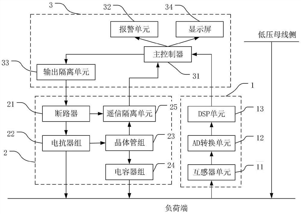
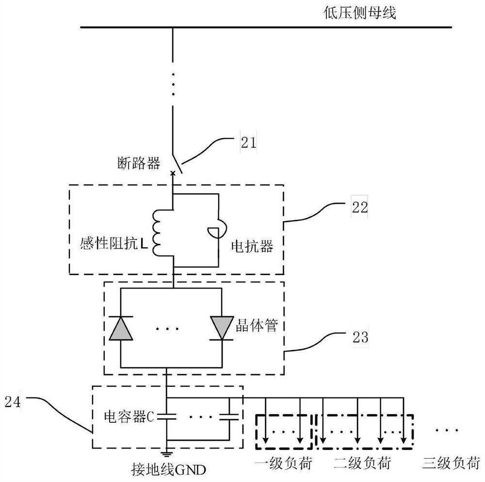
[0049] Depend on figure 1 As shown, a switching compensation system of the present invention includes the following components: a parameter sampling circuit 1 , an electric energy compensation and switching circuit 2 , and a microcomputer control circuit 3 . Among them, the parameter sampling circuit 1 is used to collect the load parameters in real time, that is, the current value and voltage value of the load, the electric energy compensation and switching ci...


PUM


Abstract

The invention discloses a switching compensation system, which comprises a parameter sampling circuit, an electric energy compensation and switching circuit and a microcomputer control circuit; the parameter sampling circuit is used for acquiring load parameters in real time and sending the load parameters to the microcomputer control circuit; the microcomputer control circuit is used for controlling the switching state of the electric energy compensation and switching circuit according to the load parameters acquired in real time so as to control the electric energy compensation and switchingcircuit to perform electric energy compensation on the load; and the electric energy compensation and switching circuit is used for carrying out electric energy compensation on a load. The electric energy compensation and switching circuit comprises a circuit breaker, a reactor group, a transistor group, a capacitor group and a remote signaling isolation unit which are connected in sequence according to a signal transmission direction. The system is simple in structure, stable and reliable in data acquisition and processing, and convenient in load electric energy monitoring, and realizes rapid and stable operation of a power grid and rapid compensation of load power consumption loss.

Description

technical field [0001] The invention relates to the technical field of electric power system automatic control, in particular to a switching compensation system. Background technique [0002] The operation of the power system requires the characteristics of intelligent and informationized power supply. The intelligent power supply mode of distributed power generation and interactive power supply requires that the sampling and error of power parameters can meet the precise control requirements, and the power consumption of the load and the total capacity match each other. Power loss and transmission can be monitored and compensated in time to ensure the stability of load power supply voltage and operation. [0003] While studying the stability and safety of the power system, the operation mode of the power supply and the model selection of the electrical equipment will be considered, and a certain power consumption capacity will be set in advance. When the load runs continuou...

Claims


Application Information

Patent Timeline
Patent Type & Authority Applications(China)
IPC IPC(8): H02J3/00
CPCH02J3/00
Inventor 欧志新段明华邓春兰彭骏王怡李队员
Owner 安徽交通职业技术学院
Why Eureka
Try Eureka