Supercharge Your Innovation With Domain-Expert AI Agents!

An Upper Die of Stamping Equipment Based on PLC Control

A stamping equipment and core mold technology, applied in the field of automation, can solve the problems of unfavorable staff health, harmful gas, high equipment cost, etc., and achieve the effect of reducing processing procedures, reducing harmful gas emissions, and reducing equipment costs

Active Publication Date: 2022-02-25
陕西能源职业技术学院
View PDF5 Cites 0 Cited by
  • Summary
  • Abstract
  • Description
  • Claims
  • Application Information

AI Technical Summary

Problems solved by technology

[0003] The above-mentioned processing method completes the processing and molding of the product through two independent processes, so the processing efficiency is low, and after the bottom plate and the side plate are stamped, due to the existence of elastic recovery, the angle between the side plate and the bottom plate is often greater than 90 degrees. Therefore, when welding the ribs in the later stage, it is necessary to clamp the side plates inwardly with the clamping tool to fully contact the ribs to complete the welding operation. The equipment cost is high and the efficiency is low.
Not only that, argon arc welding will produce more harmful gases, which is not conducive to the health of the staff

Method used


Image

  • An Upper Die of Stamping Equipment Based on PLC Control
  • An Upper Die of Stamping Equipment Based on PLC Control
  • An Upper Die of Stamping Equipment Based on PLC Control

Examples


Embodiment Construction

[0030] In order to make the techniques, creative characteristics of the present invention, it is easy to understand that the present invention is further illustrated in connection with the specific embodiments.

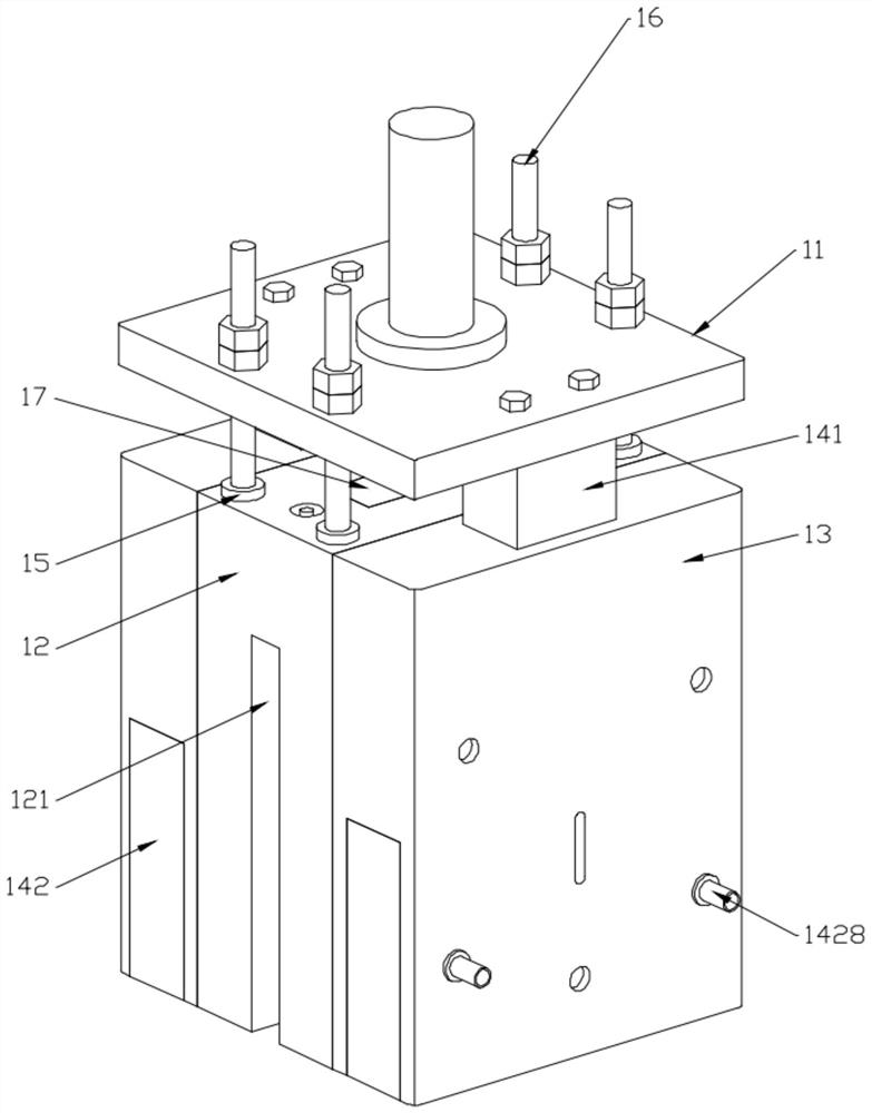
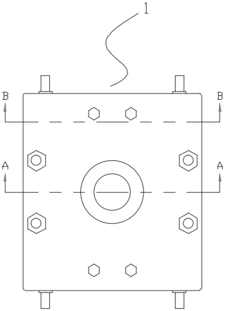
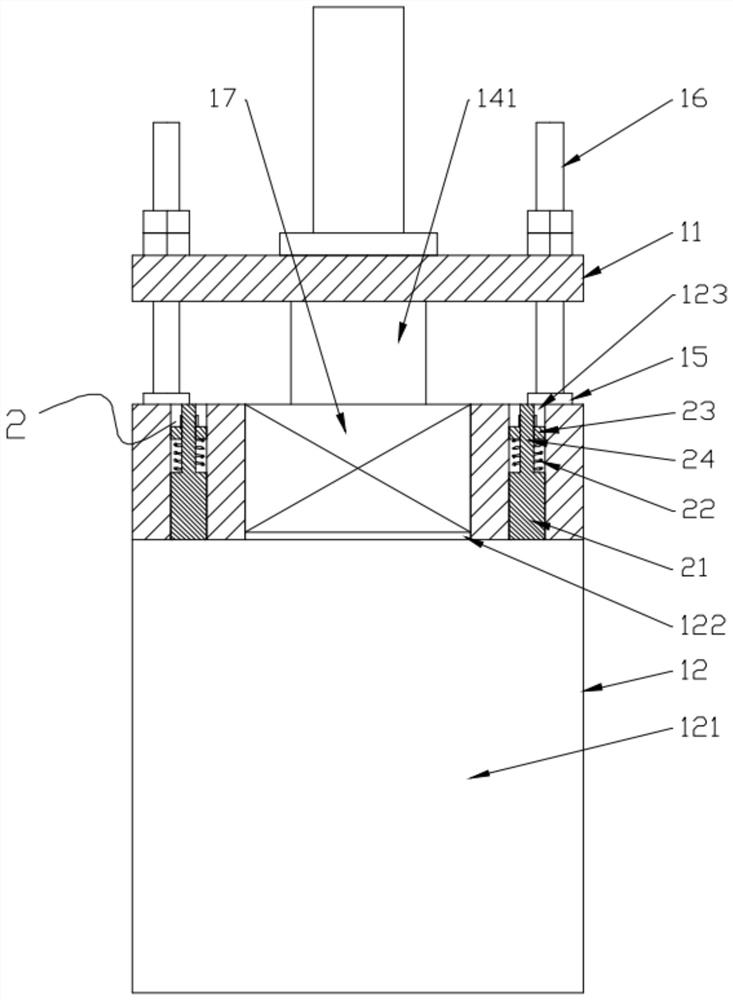
[0031] Such as Figures 1 to 12 As shown, an upper mold of a PLC-controlled stamping device includes an upper mode assembly 1 and a positive electrode conductive mechanism 4, the upper mode assembly 1 includes an upper template 11, a core mold 12, a side mold 13, and a support mechanism 14. The upper template 11 is coupled to the output of the hydraulic cylinder, and the finisher column 15 is fixed at the four corners of the upper end of the core die 12, and the upper end of the limit column 15 is fixed, and the upper template 11 slides. Connected to the guide post 16 and the lower end thereof is connected to the supporting mechanism 14, and the nut 16 is also connected to the upper template 11, which can drive the core die 12 in the upper mold plate 11, and the support me...


PUM

PropertyMeasurementUnit
thicknessaaaaaaaaaa

Abstract

The invention discloses an upper mold of stamping equipment based on PLC control, which relates to the field of automation technology, and includes an upper mold assembly and a positive electrode conductive mechanism. The invention adopts a special structure of the upper mold assembly and the positive electrode conductive mechanism installed therein , can cooperate with the lower mold and the negative electrode conductive mechanism to realize the punching and forming of the bottom plate and the side plate, and at the same time assemble the rib plate between the bottom plate and the side plate, and then energize to fix the three together by resistance welding, reducing the processing The process improves the production efficiency and reduces the equipment cost. The traditional one-piece punch design idea is abandoned. The core mold plays the role of fixing the rib plate and has a large gap with the lower mold cavity, while the centering mechanism The top block only protrudes to the outermost side during stamping and cooperates with the rib to play the role of replacing the stamping of the punch, so that the side plate can achieve the expected shape and make it fit closely with the rib, while when unloading, The top block can be retracted and out of contact with the side plate, significantly reducing the discharge force.

Description

Technical field [0001] The present invention belongs to the automation technology, and more particularly to the upper mold of a PLC-controlled stamping device. Background technique [0002] In the air conditioning system, the heat sink is typically fixed to the interior of the car through a metal, and its material has stainless steel (such as SUS430) and a cold rolled steel sheet. At present, a heat sink holder (material is SUS430), its structure Composition includes a bottom plate, two side plates, and a rib, the bottom plate and the side plate are integral structure and is formed by a U shape in advance, and then welded to the bottom plate and the side plates by argon arc welding. Among them, the thickness of the bottom plate and the side panel is 2-3 mm, and the thickness of the rib is 8-12 mm. [0003] The above processing mode is due to the completion of the product processing, the processing efficiency is low, and the bottom plate and the side panel are in the stamping, and...

Claims


Application Information

Patent Timeline
Patent Type & Authority Patents(China)
IPC IPC(8): B21D53/04B21D37/10B21D37/12B23K11/30B23K11/00B23K11/36B23K37/00
CPCB21D53/04B21D37/10B21D37/12B23K11/3009B23K11/00B23K11/36B23K37/003
Inventor 罗剑
Owner 陕西能源职业技术学院
Features
  • R&D
  • Intellectual Property
  • Life Sciences
  • Materials
  • Tech Scout
  • Unparalleled Data Quality
  • Higher Quality Content
  • 60% Fewer Hallucinations
Learn More