Eureka AIR delivers breakthrough ideas for toughest innovation challenges, trusted by R&D personnel around the world.

Gas-steam linear generator

A linear generator, gas steam technology, applied in the direction of combustion engine, internal combustion piston engine, engine operation, etc., can solve the problems of waste gas heat energy, high exhaust gas discharge speed, environmental impact, etc., and achieve simple structure, high energy efficiency and low cost Effect

Active Publication Date: 2020-11-03
陈建华
View PDF8 Cites 2 Cited by
  • Summary
  • Abstract
  • Description
  • Claims
  • Application Information

AI Technical Summary

Problems solved by technology

[0003] In practical applications, the exhaust gas discharged by the free gas linear generator has a certain pressure and kinetic energy. The greater the power, the higher the exhaust gas discharge speed; these exhaust gases with certain pressure and kinetic energy are usually discharged into the atmosphere without any treatment. Not only is the heat energy of the exhaust gas greatly wasted, but it also has an immeasurable impact on the environment and accelerates the generation of the greenhouse effect

Method used


Image

  • Gas-steam linear generator
  • Gas-steam linear generator
  • Gas-steam linear generator

Examples


Embodiment Construction

[0019] Embodiments of the present invention will be described below with reference to the drawings. Elements and features described in one drawing or one embodiment of the present invention may be combined with elements and features shown in one or more other drawings or embodiments. It should be noted that representation and description of components and processes that are not related to the present invention and known to those of ordinary skill in the art are omitted from the drawings and descriptions for the purpose of clarity.

[0020] In describing the present invention, it should be understood that the terms "center", "longitudinal", "transverse", "upper", "lower", "front", "rear", "left", "right", " The orientations or positional relationships indicated by "vertical", "horizontal", "top", "bottom", "inner" and "outer" are based on the orientations or positional relationships shown in the drawings, and are only for the convenience of describing the present invention and ...


PUM


Abstract

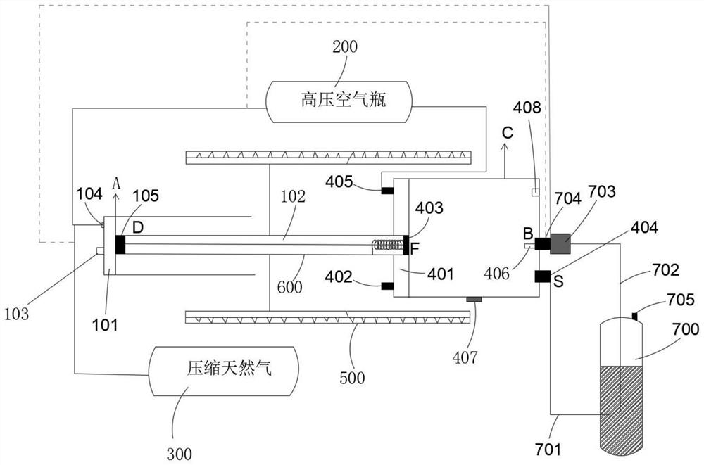
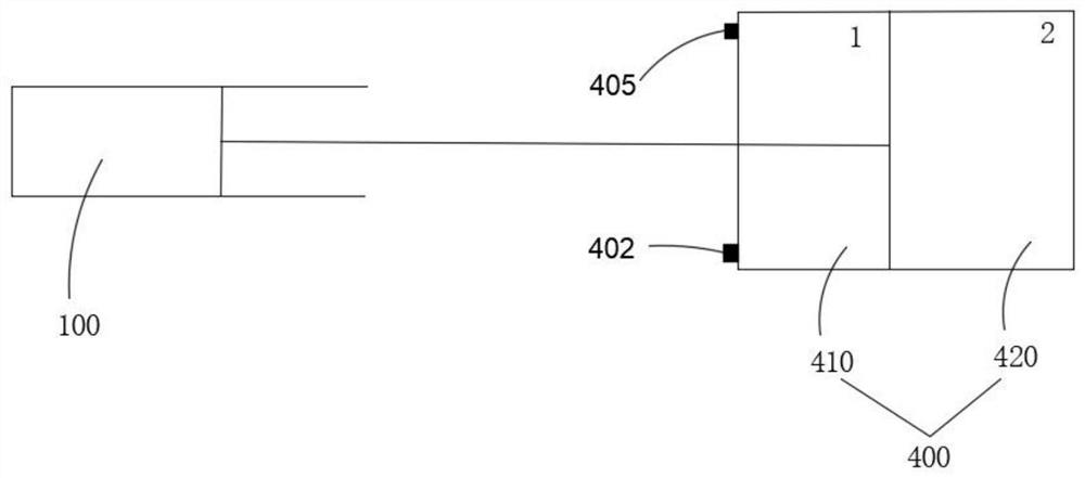
The invention discloses a gas-steam linear generator which comprises a first piston type gas power source, a second piston type steam power source, a linear generator body and a waste heat recovery device, and a connecting rod is connected with two pistons of the first piston type gas power source and the second piston type steam power source; and the linear generator comprises permanent magnets arranged on the outer sides of the first piston type fuel gas power source and the second piston type steam power source, coils arranged alternately with the permanent magnets are arranged on the outersides of the permanent magnets, and when the two pistons drive the connecting rod to reciprocate, the permanent magnets continuously reciprocate left and right in an iron core wound with the coils tocut magnetic lines of force, so that induced electromotive force is generated for power generation. The waste heat recovery device is connected with the second piston type steam power source, waste gas is discharged into the waste heat recovery device after the connecting rod performs primary reciprocating motion, after treatment by the waste heat recovery device, the waste gas serves as pushingforce of the second piston type steam power source, and therefore the problems that an existing generator wastes heat energy of the waste gas and pollutes the environment are solved.

Description

technical field [0001] The invention belongs to the technical field of waste gas recycling and generators, and in particular relates to a gas-steam linear generator based on waste heat recovery and steam conversion of waste gas. Background technique [0002] The free gas steam linear generator is directly coupled with the free piston internal combustion engine and the linear generator, and the left and right combustion chambers alternately expand and do work to drive the linear generator to reciprocate to generate electricity. The mechanical structure of this device omits the crank linkage mechanism and mechanical flywheel that convert the reciprocating motion of the piston into rotational motion, and directly uses the reciprocating motion of the piston in the combustion chamber to drive the linear motor to generate electricity, and directly converts the heat energy generated by fuel combustion into electrical energy output. The mechanical efficiency is improved, and the com...

Claims


Application Information

Patent Timeline
IPC IPC(8): F02B43/10F02B41/06F02B43/12F02B47/02F02B63/04
CPCF02B43/10F02B43/12F02B63/041F02B47/02F02B41/06F02B2043/103Y02T10/12Y02T10/30
Inventor 陈建华
Owner 陈建华
Why Eureka
Eureka Blog
Learn More