Optical fiber movable connector of a crimping-free structure

A flexible connector, crimp-free technology, applied in the direction of light guide, optics, instruments, etc., can solve the problems of increasing labor cost and equipment cost, unable to further improve assembly efficiency, assembly failure rate, etc., so as to reduce assembly failure rate. , Reduce the probability of safety accidents and ensure the effect of stability

Pending Publication Date: 2020-11-03
CHANGZHOU TAIPING COMM SCI & TECH
View PDF0 Cites 1 Cited by
  • Summary
  • Abstract
  • Description
  • Claims
  • Application Information

AI Technical Summary

Problems solved by technology

In the assembly process of the existing optical fiber connectors, it is necessary to use the crimping process to fix the optical cable. Not only the structure is cumbersome, but also the cost of man-hours and equipment costs will be increased. At the same time, the crimping process also has a certain assembly failure rate, which cannot further improve the assembly. Efficiency, especially the small size of each part of the optical fiber active connector, using a press to crimp is likely to cause injury to employees during operation, and there is a certain risk of operational safety

Method used


Image

  • Optical fiber movable connector of a crimping-free structure
  • Optical fiber movable connector of a crimping-free structure
  • Optical fiber movable connector of a crimping-free structure

Examples


Embodiment Construction

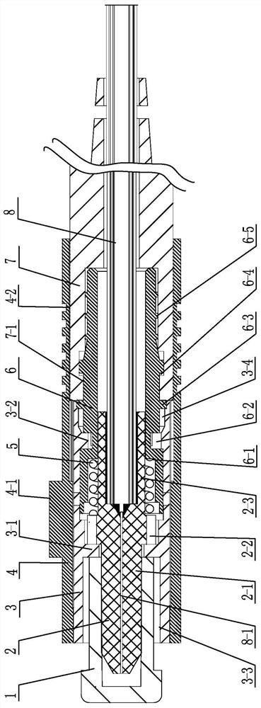
[0019] See figure 1 As shown, the optical fiber active connector of the crimp-free structure of the present invention includes an inner sleeve 3 , a connecting sleeve 6 , an outer sleeve 4 , a ceramic ferrule 2 and a sheath tube 7 .

[0020] See figure 1 As shown, the inner sleeve 3 of the present invention includes a front limiting hole 3-3 for matching with the adapter when docking, a shoulder 3-1 for limiting the position of the tailstock with groove 2-2 and a shoulder for connecting with the connecting sleeve. 6. The rear mounting hole 3-4 of the connection is fixed by the inner sleeve 3 and the adapter during docking, and the outer protrusion 4-1 on the outer sleeve 4 is clamped and fixed to prevent the connector from being displaced and affecting the docking performance. See figure 1 As shown, the dustproof cap 1 of the present invention is tightly sleeved on the ceramic pin 2 and extends into the inner sleeve 3, and is limited by the shoulder 3-1. The present inventio...


PUM


Abstract

The invention relates to an optical fiber movable connector of a crimping-free structure. The optical fiber movable connector comprises an inner sleeve, a connecting sleeve, an outer sleeve, a ceramicpin and a sheath tube, the connecting sleeve comprises a first shaft section connected with the inner sleeve and a second shaft section connected with the sheath pipe, a stepped hole in the front side of the first shaft section is communicated with a through hole of the second shaft section, the first shaft section is clamped in a rear mounting hole of the inner sleeve, and the second shaft section is clamped in a front mounting hole of the sheath pipe; the ceramic contact pin is arranged between the inner sleeve and the connecting sleeve, two ends of the spring sleeved on the contact pin tail handle are respectively abutted against a grooved tailstock of the ceramic contact pin and an annular table of a stepped hole of the connecting sleeve, the single-core optical fiber is fixed in a core hole of the plug base, and aramid fiber and outer skin of the optical cable are fixed in a fixing hole through epoxy resin glue. The optical cable penetrates out of the connecting sleeve and the sheath tube; and the outer sleeve is sleeved on the inner sleeve and is screwed on the inner threaded hole of the protective sleeve. The connector is reasonable in structure, good in assembly process, capable of improving the assembly efficiency and reducing the assembly reject ratio, and safe and reliable to operate.

Description

technical field [0001] The invention relates to an optical fiber active connector with a crimp-free structure, belonging to the technical field of optical fiber connectors on optical communication devices. Background technique [0002] Optical fiber connector is the most widely used optical passive device in the optical fiber communication system. It is a device for detachable connection between optical fiber and optical fiber. It can be coupled into the receiving optical fiber to the greatest extent, and minimize the impact on the system due to its intervention in the optical link. [0003] Optical fiber connectors usually consist of ceramic ferrules, connecting sleeves, springs, inner sleeves, and sheath tubes. The core is placed between the connecting sleeve and the inner sleeve, while the part of the optical cable with aramid and the unstripped optical cable pass through the ceramic ferrule and the connecting sleeve. In order to ensure that the optical cable finally mee...

Claims


Application Information

Patent Timeline
Patent Type & Authority Applications(China)
IPC IPC(8): G02B6/38
CPCG02B6/3855G02B6/3874
Inventor 刘志清吴锦辉石新根任献忠
Owner CHANGZHOU TAIPING COMM SCI & TECH
Why Eureka
Try Eureka