High-temperature submersible motor protector

An oil-submersible motor and protector technology, which is applied to machines/engines, electromechanical devices, electrical components, etc., can solve problems such as increased vibration, reduced motor shaft rigidity, and reduced lubricating oil viscosity. The effect of lowering the temperature

Pending Publication Date: 2020-11-03
TONGYI TECH CO LTD SHENYANG UNIV OF TECH
View PDF0 Cites 0 Cited by
  • Summary
  • Abstract
  • Description
  • Claims
  • Application Information

AI Technical Summary

Problems solved by technology

The thrust bearing of traditional motor protectors is often located at the bottom of the protector close to the motor. For high-temperature motor protectors, the thrust bearing close to the motor means that the heat from the motor winding is easily transferred to the thrust bearing, causing the temperature at the thrust bearing to rise significantly. , the viscosity of the lubricating oil decreases, resulting in a decrease in the bearing capacity of the thrust bearing and prone to gluing failure of the bearing
In addition, the thrust bearing of the protector is close to the motor, and the structure is too close to the thrust bearing of the motor shaft inside the motor. The vibration of the two pairs of thrust bearings interferes with each other, which aggravates the vibration
Thrust bearings located at the bottom of the protector tend to distort the motor shaft and reduce the rigidity of the motor shaft

Method used


Image

  • High-temperature submersible motor protector
  • High-temperature submersible motor protector
  • High-temperature submersible motor protector

Examples


Embodiment 1

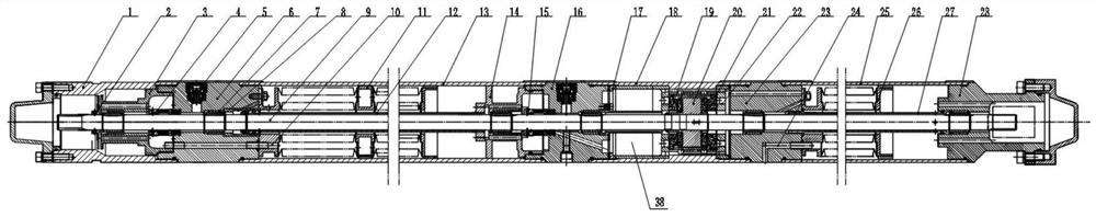
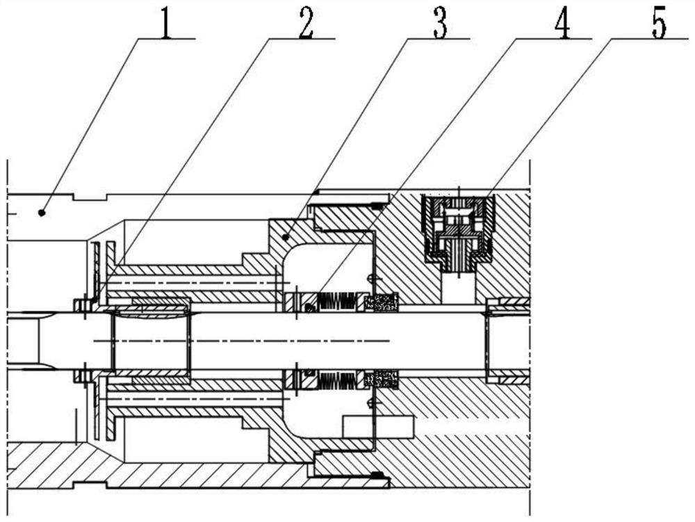
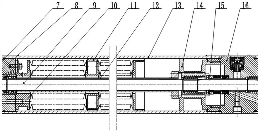
[0030] like Figure 1-5 As shown, this embodiment provides a high-temperature submersible motor protector, including a sand rejection chamber, an upper balance chamber, a thrust bearing chamber, a lower balance chamber, a protector tailstock 28 and a protector shaft 9 that runs through the entire protector.

[0031] The sand throwing chamber includes a sand throwing chamber shell 1, the sand throwing chamber shell 1 is connected to the protector head connecting body 6 through threads, and the sand throwing wheel 2 is fixed on the protector shaft 9 with set screws, and can be attached to the protector The shaft 9 rotates to throw the sand in the well fluid to the inner wall of the sand rejection chamber shell 1, and then deposits in the gap between the first support body 3 and the sand rejection chamber shell 1, so that the sand particles installed on the first support The sand content of the well fluid around the first-stage mechanical seal 4 in the inner cavity of the body 3 ...

Embodiment 2

[0038] This embodiment provides a high-temperature submersible motor protector, which is different from Embodiment 1 in that the number of lower balance chambers is three.

[0039] The high-temperature submersible motor protector provided by the specific embodiment of the present invention has specific advantages in the following four aspects:

[0040] 1. The thrust bearing of the protector of the present invention is located between the upper balance cavity and the lower balance cavity, and is separated from the high-temperature motor by at least one lower balance cavity. The temperature of the heated motor oil in the motor winding will drop significantly after passing through the lower balance cavity. Lowering the temperature of the motor oil in the thrust bearing cavity is beneficial to the normal operation of the thrust bearing, and is also conducive to heat dissipation during the circulation of the motor oil, thereby reducing the internal temperature of the motor.

[0041...


PUM


Abstract

The invention provides a high-temperature submersible motor protector, and the protector comprises a thrust bearing, wherein the thrust bearing is arranged in the middle of the protector and located in a thrust bearing cavity, and an upper end balance cavity and a lower end balance cavity are formed in the upper end and the lower end of the thrust bearing cavity respectively. The thrust bearing cavity is communicated with an inner cavity of the high-temperature submersible motor through the lower end balance cavity; the protector further comprises a protector shaft penetrating through the whole protector. According to the invention, normal work of the thrust bearing is facilitated, heat dissipation in the motor oil circulation process is also facilitated, the internal temperature of the motor is further reduced, distortion of the protector shaft is reduced, and the rigidity of the protector shaft is improved.

Description

technical field [0001] The invention belongs to the technical field of high-temperature oil well lifting, and relates to a submersible motor protector, in particular to a high-temperature submersible motor protector. Background technique [0002] The high-temperature motor protector is one of the key components of the high-temperature submersible electric pump. Its function is mainly to maintain the pressure balance inside and outside the motor cavity and prevent well fluid from entering the motor. The motor protector bears the axial force from the pump through the thrust bearing, and transmits the torque from the motor shaft to the pump shaft through the protector shaft. The thrust bearing of traditional motor protectors is often located at the bottom of the protector close to the motor. For high-temperature motor protectors, the thrust bearing close to the motor means that the heat from the motor winding is easily transferred to the thrust bearing, causing the temperature ...

Claims


Application Information

Patent Timeline
Patent Type & Authority Applications(China)
IPC IPC(8): H02K5/132H02K5/10H02K7/08H02K9/19H02K5/04F04D13/08F04D29/044F04D29/046F04D29/42F04D29/58
CPCF04D13/086F04D29/044F04D29/046F04D29/426F04D29/5806F04D29/586H02K5/04H02K5/10H02K5/132H02K7/08H02K9/19
Inventor 季文纲李延斌孙兴革张义顺彭兵李爱秋邵林王德忠
Owner TONGYI TECH CO LTD SHENYANG UNIV OF TECH
Why Eureka
Try Eureka