
Suspension structure of suspension type permanent magnet magnetic levitation rail transit equipment

A technology for maglev tracks and transportation equipment, which is applied to elevated railway systems using suspended vehicles, funicular railways, transportation and packaging, etc., and can solve problems affecting turning radius and turning speed, short braking distance, and increasing suspension pressure. Achieve the effect of accurately guaranteeing parallelism, stable guiding distance and ensuring smoothness

Active Publication Date: 2020-11-06
江西永磁磁浮科技有限责任公司
View PDF10 Cites 3 Cited by
  • Summary
  • Abstract
  • Description
  • Claims
  • Application Information

AI Technical Summary

Problems solved by technology

The smaller the distance between the two walls of the existing "inverted U" structure will lead to greater guiding resistance; the larger the distance will lead to smaller guiding force, and even the guide wheel will break away from the wall
Since the sky beam is a large-scale welded structure, and the mechanism is U-shaped, after welding, the interior cannot be machined, so it is difficult to ensure the verticality of the wall surface and the top surface
After welding, the distance between the two side walls cannot be guaranteed, so the amount of spring compression changes constantly, which will cause the guiding force to fluctuate and affect the stability of the guiding
Moreover, due to the change of the inner wall spacing, the relative position of the permanent magnet block and the permanent magnet rail in the horizontal direction changes, which makes the distance between the upper and lower guide wheels different, resulting in frequent fluctuations in the suspension force and affecting the stability of the suspension;
[0004] 2. In the suspension system, the support arm is welded on the inner wall of the sky beam, and the permanent magnet rail is installed on the support arm inside the sky beam. In the actual processing process, because the support arm is inside the sky beam, it is difficult to process after welding. The first difficulty is To ensure the straightness of the two support arms, it is easy to have a curved structure with ups and downs; secondly, it is difficult to ensure the level of the two rows of permanent magnet rails in the vertical plane, that is, the two rows of permanent magnet rails are high and the other is low, resulting in two rows of left and right bogies. Different side heights affect the stability of the suspension;
[0006] 4. The system is guided by the rubber wheels on the bogie, and the guiding force is provided by springs. In practice, first of all, the elastic force between the springs cannot be guaranteed to be consistent; secondly, the rubber wheels are both guide wheels and brake wheels. If the spring If the force is too large, the guiding resistance will be too large, which will speed up the wear of the rubber tire and the consumption of driving energy, but the braking distance will be shorter at this time; Since the friction force is small, the braking distance will be greatly lengthened, so there is a contradiction between the guiding force and the braking force;
[0007] 5. The sky beam is an inverted U shape, and all system components are installed inside, which is not conducive to subsequent maintenance
[0009] A) Linear motors are installed in cn109056431A and cn109131370A, and a frame beam is connected between the front and rear bogies. The stator part of the linear motor is installed above the frame beam, and the linear motor mover (induction Plate) forms a driving circuit to push the car to run, and the frame beam is long in size and heavy in weight, which firstly increases the suspension pressure, and secondly, the frame beam is inside the sky beam, which seriously affects the turning radius and turning speed;
[0010] B) The guide wheels in this system are guided outwards. When turning, due to the action of centrifugal force, the force on one side of the guide wheel will increase, and the compression of the spring will increase, and the force on the other side of the guide wheel will decrease. will decrease, and the spring will become looser and looser, so the entire bogie will "miss" and deviate to one side (that is, sideways), and the magnetic block on the bogie and the magnetic track on the sky beam will also deviate seriously, resulting in suspension The force is greatly reduced, which seriously affects the suspension stability

Method used


Image

  • Suspension structure of suspension type permanent magnet magnetic levitation rail transit equipment
  • Suspension structure of suspension type permanent magnet magnetic levitation rail transit equipment
  • Suspension structure of suspension type permanent magnet magnetic levitation rail transit equipment

Examples


Embodiment Construction

[0049] In order to make the purpose and technical solutions of the embodiments of the present invention more clear, the technical solutions of the embodiments of the present invention will be clearly and completely described below in conjunction with the drawings of the embodiments of the present invention. Apparently, the described embodiments are some, not all, embodiments of the present invention. Based on the described embodiments of the present invention, all other embodiments obtained by persons of ordinary skill in the art without creative efforts shall fall within the protection scope of the present invention.

[0050] Those skilled in the art can understand that, unless otherwise defined, all terms (including technical terms and scientific terms) used herein have the same meaning as commonly understood by those of ordinary skill in the art to which this invention belongs. It should also be understood that terms such as those defined in commonly used dictionaries shoul...


PUM


Abstract

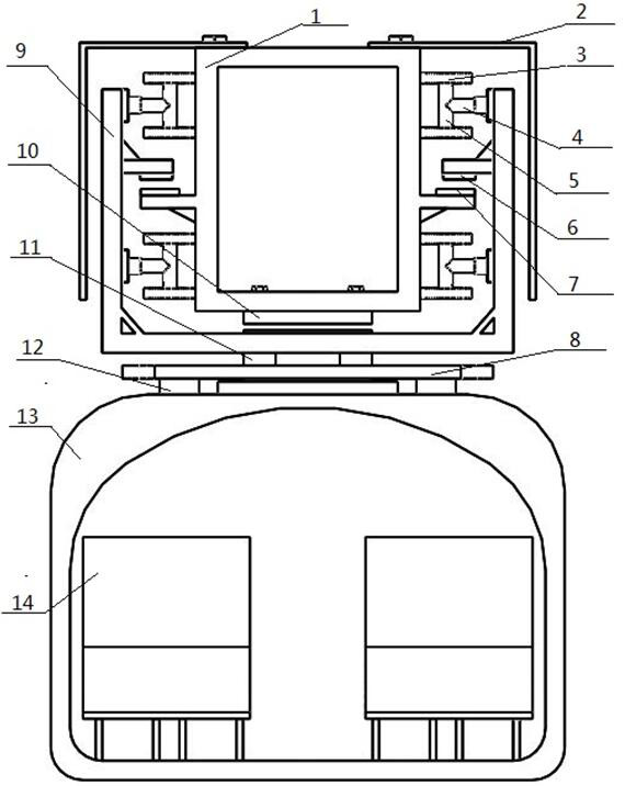
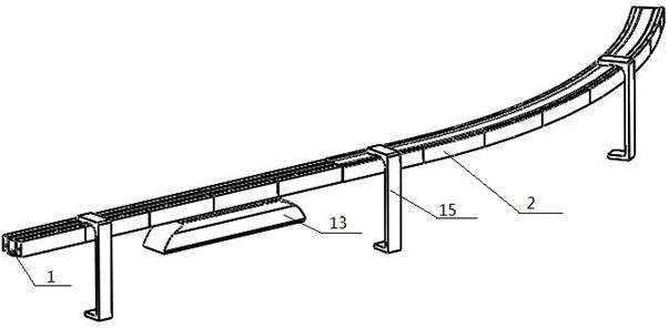
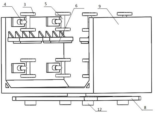
The invention discloses a suspension structure of suspension type permanent magnet magnetic levitation rail transit equipment. Through a sky beam, permanent magnet rails, a bogie, permanent magnet blocks, hydraulic cylinders, rubber wheels, side plates and connecting plates, a lift car and the sky beam are subjected to suspension separation, a driving system between the connecting plates and the sky beam is used for providing power, the bogie is used for providing guidance, and the lift car is driven to move in the sky beam track direction. According to the invention, the sky beam is set as asquare closed structure and can be conveniently formed through welding or direct casting, and the permanent magnet rails are arranged outside the formed sky beam, so that machining is convenient; thedistance, parallelism and planeness of the two side walls of the bogie are accurately guaranteed, the stable guide distance is guaranteed, guide force cannot be suddenly changed, stable guide is guaranteed, and noise generated when the rail transit equipment runs is reduced.

Description

technical field [0001] The invention relates to the field of rail transit equipment, in particular to a suspension structure of suspended permanent magnet maglev rail transit equipment. Background technique [0002] Chinese patent cn109056431A and patent cn109131370A disclose a suspended permanent magnet maglev rail transit system and mechanical structure, which is a new type of low-speed maglev transportation system, including columns, sky beams, suspension systems, linear motors, guide systems, bogies, The car has a C-shaped column with a height of about 10 meters. One end is fixed on the ground and the other end is suspended from the sky beam. The suspension system, linear motor, guiding system, bogie and safety protection system are all arranged inside the sky beam. There is a support arm on the inner side, and a permanent magnet array is installed on the support arm, which interacts with the permanent magnet array installed at the lower end of the bogie to generate repu...

Claims


Application Information

Patent Timeline
IPC IPC(8): B61B12/02B61B12/00B61B3/02B61F5/52
CPCB61B3/02B61B12/00B61B12/02B61F5/52
Inventor 占鹏飞邓永芳杨杰苏彬彬
Owner 江西永磁磁浮科技有限责任公司
Learn More