

Method for preparing graphene by arc method
A technology of graphene and arc method, which is applied in the field of graphene preparation by arc method, can solve the problems of low production capacity and large-scale industrialization, and achieve the effects of improving efficiency, good quality and high purity
- Summary
- Abstract
- Description
- Claims
- Application Information
AI Technical Summary
Problems solved by technology
Method used
Image

Examples
Embodiment 1
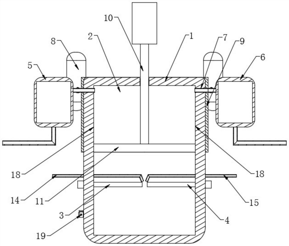
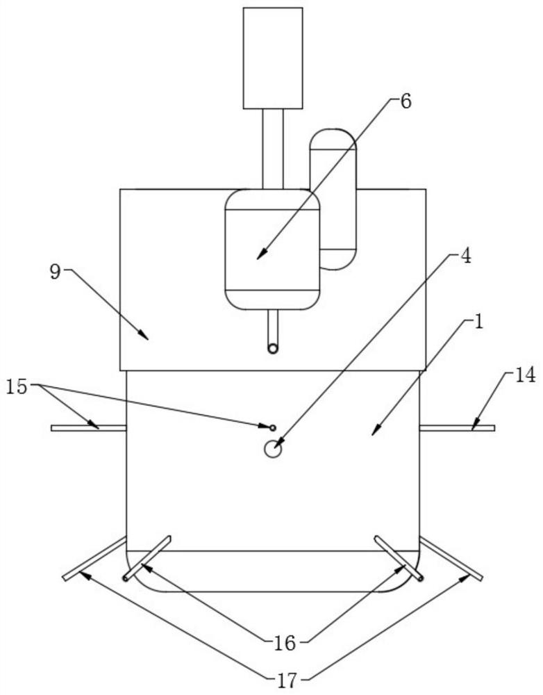
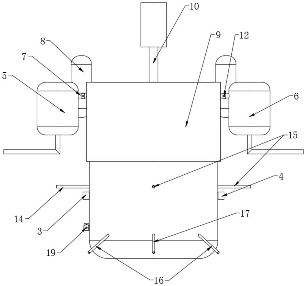
[0044] Use arc method to prepare the equipment of graphene, described equipment comprises columnar reaction chamber, cathode and anode graphite rod, graphene, gas input pipeline. Wherein the distance between the cathode and cathode graphite rods is 3mm. The graphene comprises a collection push-pull positioned at the top of the columnar reaction chamber, a graphene collector positioned outside the columnar reaction chamber, and a cooling jacket set in the upper region of the columnar reaction chamber; the collection push-pull It comprises a push-pull rod and a hollow annular push plate, and a central connection of three connecting ribs of the push-pull rod and the hollow annular push plate. The outer diameter of the circular push plate is 0.1 mm smaller than the inner diameter of the columnar reaction chamber, and the inner diameter of the annular push plate is 70 mm smaller than the outer diameter. The collector is two symmetrically placed collector I and collector II, and th...
Embodiment 2
[0047] Use arc method to prepare the equipment of graphene, described equipment comprises columnar reaction chamber, cathode and anode graphite rod, and anode and cathode graphite rod automatic delivery part, graphene, gas input pipeline. Wherein the distance between the cathode and anode graphite rods is 2mm. The graphene comprises a collection push-pull positioned at the top of the columnar reaction chamber, a graphene collector positioned outside the columnar reaction chamber, and a cooling jacket set in the upper region of the columnar reaction chamber; the collection push-pull It comprises a push-pull rod and a hollow annular push plate, and a central connection of three connecting ribs of the push-pull rod and the hollow annular push plate. The outer diameter of the circular push plate is 0.2 mm smaller than the inner diameter of the columnar reaction chamber, and the inner diameter of the annular push plate is 50 mm smaller than the outer diameter. The collectors are t...
Embodiment 3
[0050] Other conditions and parameter are identical with embodiment 1, and difference is, the outlet of regulating each pipeline gas is apart from intersection point 100mm between cathode and anode. The production capacity of graphene reaches 5.17kg per hour. After testing, the purity of graphene is 99.9%.
PUM
 Abstract
Description
Claims
Application Information