Cooling-water machine with dual-temperature double-control system structure

A system structure, chiller technology, applied in the direction of refrigerators, refrigeration components, refrigeration and liquefaction, etc., can solve the problems of increasing the refrigeration load of the chiller, increasing the power of the whole machine, unsafe faults, etc. Large condensation area and safe use

Pending Publication Date: 2020-11-06
东莞市春益科技有限公司
View PDF0 Cites 1 Cited by
  • Summary
  • Abstract
  • Description
  • Claims
  • Application Information

AI Technical Summary

Problems solved by technology

[0003] The existing dual-temperature dual-control system structure of the chiller uses a heater to heat and output hot water, and the heating pipe is powered by 220V high voltage, which is unsafe and has many faults
The other channel uses a compressor to compress and refrigerate to output low-temperature water, and the two channels of water return to a bucket at the same time. This type of dual-temperature output chiller system increases the cooling load of the chiller due to the addition of a heater on the water channel. At the same time, the whole machine The power will increase, resulting in low efficiency

Method used


Image

  • Cooling-water machine with dual-temperature double-control system structure

Examples


Embodiment 1

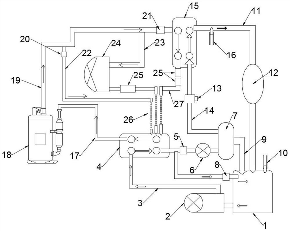
[0025] see figure 1 As shown, a chiller with a dual-temperature dual-control system structure includes a bucket 1, a cold-heat exchanger II4, a water storage 7, a cold-heat exchanger I15, a compressor 18, and a condenser 24. The compressor 18 The high-temperature gas outlet is connected to the high-pressure exhaust pipe 19, and the high-pressure exhaust pipe 19 is connected to the refrigerant input port of the cold-heat exchanger I15. The high-pressure exhaust pipe 19 at the refrigerant input port of the cold-heat exchanger I15 is equipped with a solenoid valve I21. The refrigerant output port of the cold heat exchanger I15 is connected to the air outlet pipe 27, and a filter 25 is installed on the air outlet pipe 27, and the air outlet pipe 27 is connected to the throttle valve 26, and the throttle valve 26 is connected to the refrigerant input port of the cold heat exchanger II4, The refrigerant output port of the cold heat exchanger II4 is connected to the air return port o...

Embodiment 2

[0036] The chiller with dual-temperature dual-control system structure as described in Example 1 includes a bucket 1, a cold heat exchanger II4, a water storage 7, a cold heat exchanger I15, a compressor 18, and a condenser 24. The high-temperature gas outlet of the machine 18 is connected to the high-pressure exhaust pipe 19, and the high-pressure exhaust pipe 19 is connected to the refrigerant input port of the cold heat exchanger I15, and the refrigerant output port of the cold heat exchanger I15 is connected to the air outlet pipe 27, and the air outlet pipe 27 is equipped with The filter 25 and the air outlet pipe 27 are connected to the throttle valve 26, and the throttle valve 26 is connected to the refrigerant input port of the cold heat exchanger II4, and the refrigerant output port of the cold heat exchanger II4 is connected to the air return port of the compressor 18 through the suction pipe 17.

[0037] The cold heat exchanger II4 is connected to the water pump 2 thro...


PUM


Abstract

The invention discloses a cooling-water machine with a dual-temperature double-control system structure and belongs to the technical field of cooling-water machines. The cooling-water machine comprises a water bucket, a second cool-heat-exchanger, a water receiver, a first cool-heat-exchanger, a compressor and a condenser; through additionally arranging an electromagnetic valve, the first cool-heat-exchanger and the second cool-heat-exchanger, on and off of the electromagnetic valve are intelligently controlled through software; the temperature of exhaust gas of the compressor is utilized andis conducted to water through the first cool-heat-exchanger to heat and output, and one path of high temperature water and one path of low temperature water are outputted on the working condition of not increasing any load of the cooling-water machine system; at the same time, as the heat of the exhaust gas of the compressor is absorbed by low temperature water, and it is equivalent to increasingthe condensing area of the cooling-water machine during the refrigerating process, the refrigerating efficiency of the cooling-water machine system is greatly improved; and in a dual-temperature double-control system realizing the equal effect, the cooling-water machine replaces a thermal fuse, saves energy, greatly improves the energy-saving efficiency, and is safer to use and high in practicality.

Description

technical field [0001] The invention relates to the technical field of water chillers, in particular to a water chiller with a dual-temperature dual-control system structure. Background technique [0002] Chiller is a kind of water cooling equipment, which can provide constant temperature, constant flow and constant pressure cooling equipment. The principle of the chiller is to inject a certain amount of water into the internal water tank of the machine, cool the water through the chiller refrigeration system, and then have a water pump inside the machine to inject low-temperature frozen water into the equipment that needs to be cooled, and the chilled water will cool the water inside the machine. The heat is taken away, and the high-temperature hot water is returned to the water tank to cool down again, so that the cooling is circulated and exchanged to achieve the effect of cooling the equipment. [0003] The existing dual-temperature dual-control system structure of the ...

Claims


Application Information

Patent Timeline
IPC IPC(8): F25B41/00F25B41/04
Inventor 甘廖师
Owner 东莞市春益科技有限公司
Why Eureka
Try Eureka