
Lead-bismuth anode mud smelting converter

An anode slime and converter technology, which is applied in the field of smelting converters, can solve problems such as reducing device safety, increasing processing costs, and molten liquid leakage, and achieves the effects of improving production efficiency, improving safety, and preventing leakage.

Active Publication Date: 2020-11-06
贵溪三元金属有限公司
View PDF5 Cites 2 Cited by
  • Summary
  • Abstract
  • Description
  • Claims
  • Application Information

AI Technical Summary

Problems solved by technology

[0003] The existing smelting converter generally does not have its own rotating device. When rotating, the bottom of the smelting converter needs to be pulled by a lifting device to realize its own rotation. The operation is cumbersome, and an additional lifting device is required, which increases the processing cost of the device. , when the lifting device is rotating, it may cause the melting converter to shift, which may cause the leakage of the melt and reduce the safety of the device
[0004] When the existing smelting converter is smelting, there may be residues sticking to the inner wall of the smelting converter. After the device has been running for a period of time, the device needs to be shut down to clean the inner wall of the smelting converter to prevent the residue from sticking to the inner wall of the smelting converter for a long time. On the inner wall, but when the device is cleaning, it cannot work, which reduces the production efficiency of the device
[0005] When the existing smelting converter smelts raw materials, it will produce melt and slag, which need to be salvaged separately. The process requires the use of professional fishing tools, and the operation is complicated, which increases the labor intensity of the operator

Method used


Image

  • Lead-bismuth anode mud smelting converter
  • Lead-bismuth anode mud smelting converter
  • Lead-bismuth anode mud smelting converter

Examples


Embodiment Construction

[0030] The following will clearly and completely describe the technical solutions in the embodiments of the present invention with reference to the accompanying drawings in the embodiments of the present invention. Obviously, the described embodiments are only some, not all, embodiments of the present invention. Based on the embodiments of the present invention, all other embodiments obtained by persons of ordinary skill in the art without making creative efforts belong to the protection scope of the present invention.

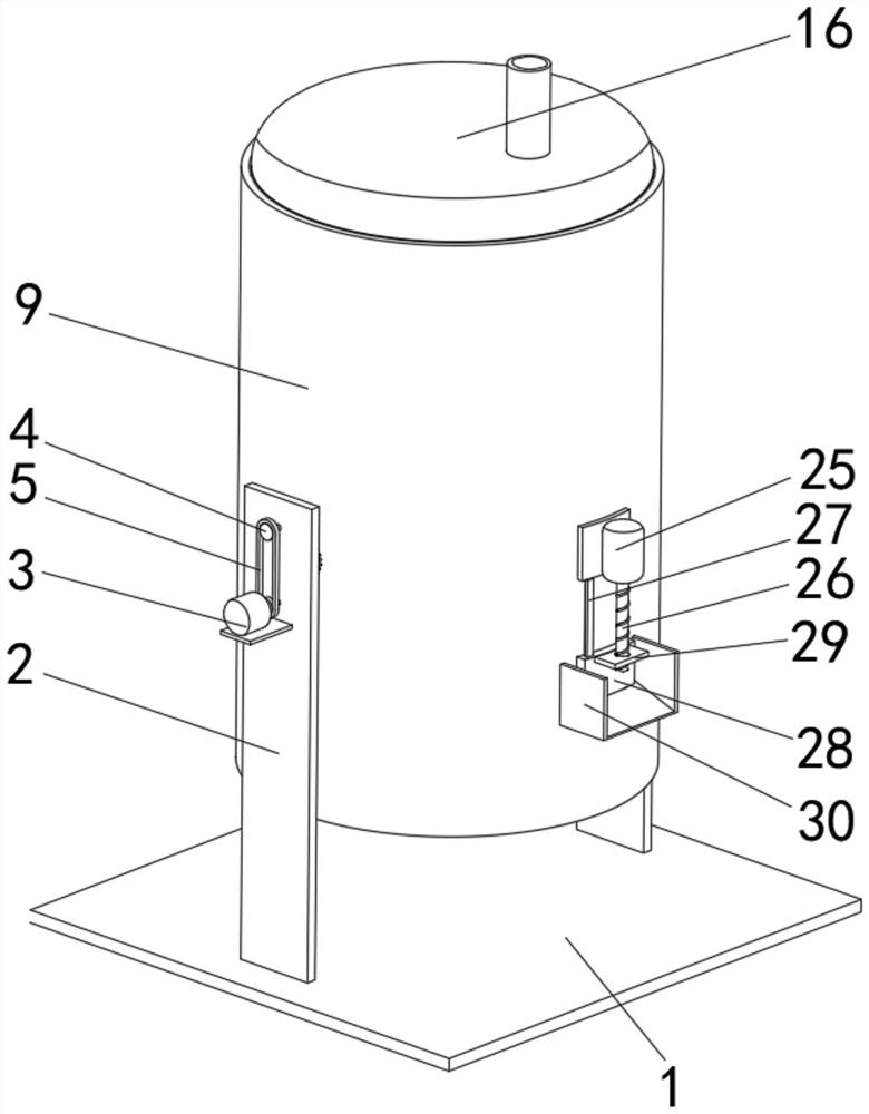
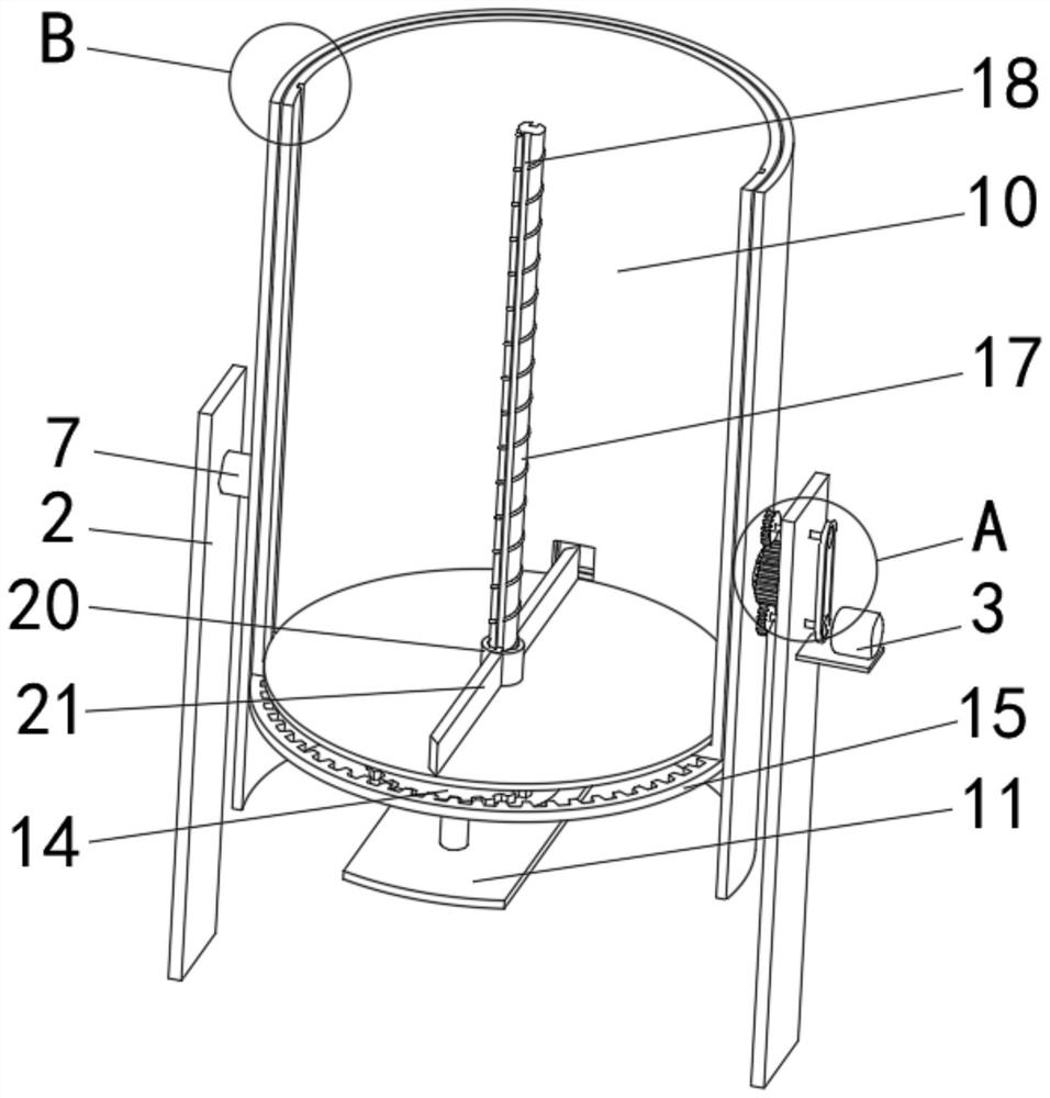
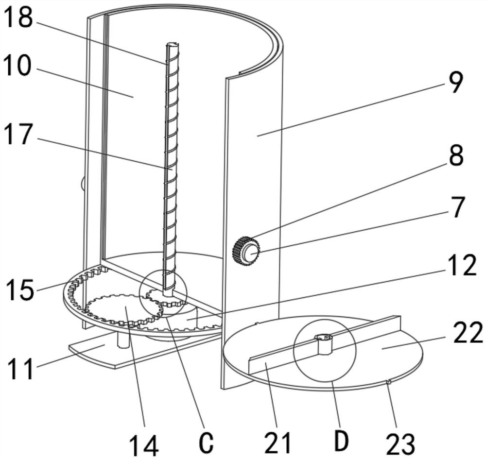
[0031] see Figure 1-9, a lead-bismuth anode slime smelting converter, comprising a base plate 1, a support plate 2 is fixedly installed on the top surface of the base plate 1, a motor-3 is fixedly installed on the front side of the support plate 2, and a pulley is movably connected to the front side of the support plate 2 4. There are two pulleys 4 and two half gears 6. The two half gears 6 are respectively located above and below the gear one 8. The two half...


PUM


Abstract

The invention relates to the technical field of smelting converters, and discloses a lead-bismuth anode mud smelting converter comprising a bottom plate. A supporting plate is fixedly installed on thetop face of the bottom plate. A first motor is fixedly installed on the front side face of the supporting plate. The front side face of the supporting plate is movably connected with belt wheels. Thesurfaces of the belt wheels are in transmission connection with a belt. A half-toothed gear is fixedly installed on the rear side face of each belt wheel. The rear side face of the supporting plate is movably connected with a connection shaft. According to the lead-bismuth anode mud smelting converter, by means of meshing of the two half-toothed gears and a first gear, the first gear can drive afixed barrel to swing in the vertical direction through the connection shaft; a second gear is driven by a second motor to rotate, and by means of meshing of the second gear and a third gear and meshing of the third gear and a gear ring, the second motor can drive a converter body to rotate in the fixed barrel through the gear ring; it is avoided that rotation is conducted through a hoisting device, it is avoided that the smelting converter deviates, leakage of molten liquid is prevented, and safety of the device is improved.

Description

technical field [0001] The invention relates to the technical field of smelting converters, in particular to a lead-bismuth anode slime smelting converter. Background technique [0002] The furnace body of the smelting converter can be rotated. It is used for metallurgical furnaces for blowing steel or mirrors. Important steelmaking equipment can also be used for copper and nickel smelting. Converters are divided into alkaline and acidic converters according to the refractory properties of the lining; The gas used in blowing is divided into air converter and oxygen converter. In the refining of lead-bismuth anode slime, a smelting converter is required for processing. [0003] The existing smelting converter generally does not have its own rotating device. When rotating, the bottom of the smelting converter needs to be pulled by a lifting device to realize its own rotation. The operation is cumbersome, and an additional lifting device is required, which increases the proces...

Claims


Application Information

Patent Timeline
IPC IPC(8): F27B17/00F27D3/15F27D25/00C22B7/00C22B13/02C22B30/06
CPCF27B17/00F27D3/1545F27D25/001C22B7/001C22B13/025C22B30/06Y02P10/20
Inventor 吴世军黄志荣
Owner 贵溪三元金属有限公司
Learn More