Cam measuring device and cam measuring method based on laser interference principle

A technology of laser interference and measuring device, applied in the field of precision measurement, can solve the problems of large Abbe error, reduced cam measurement accuracy, inability to apply various cam measurements, etc., and achieves the effect of reducing Abbe error and strong independence

Pending Publication Date: 2020-11-06
NAT INST OF METROLOGY CHINA
View PDF2 Cites 1 Cited by
  • Summary
  • Abstract
  • Description
  • Claims
  • Application Information

AI Technical Summary

Problems solved by technology

In this type of instrument, the grating ruler is not only used as the length measuring unit of each coordinate axis, but also as the feedback control unit for the movement of each coordinate axis. It is generally arranged near the X, Y, and Z guide rails, far away from the measured point of the cam. Due to the existence of guide rails A certain angular pendulum error, so as to produce a large Abbe error, which greatly reduces the measurement accuracy of the cam
At the same time, for the measurement of multiple error items of the cam, the existing measurement principle cannot avoid the influence of the displacement between the measurement optical paths for the measurement of the lift value of different cams, so it cannot be applied to the measurement of various cams

Method used


Image

  • Cam measuring device and cam measuring method based on laser interference principle
  • Cam measuring device and cam measuring method based on laser interference principle
  • Cam measuring device and cam measuring method based on laser interference principle

Examples


Embodiment 1

[0035] This embodiment provides the measurement method for disc cam:

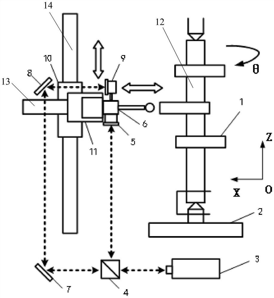
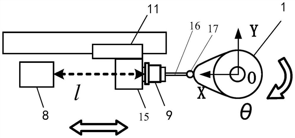
[0036] Such as Figure 1-2As shown, the camshaft 12 is clamped with the upper and lower centers, the lower center rotary shaft system 2 drives the camshaft 12 to the zero position of the angle, and the micrometer probe 6 moves along the Z axis through the Z axis guide rail 14 to the position of the cam under test. Intermediate section height. After the measurement starts, the laser measurement value in the X-axis direction is cleared, and the X-axis slider 11 on the X-axis guide rail 13 drives the micrometer probe 6 to touch the cam surface, and the micrometer probe 6 to be measured is at the X-axis offset value After reaching the set threshold, the micrometer probe 6 sends a trigger signal to the host computer control system, and the control system collects the current laser length measurement value l 1 and the angle value of the rotary shaft system θ 1 . The micrometer probe 6 keeps in contact with th...

Embodiment 2

[0038] This embodiment provides the measuring method for cylindrical cam:

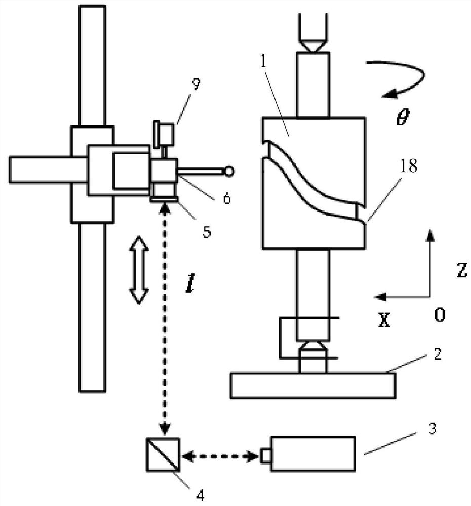
[0039] Such as image 3 As shown, the camshaft 12 is clamped with the upper and lower centers, the lower center rotary shaft system 2 drives the camshaft 12 to the zero position of the angle, and the micrometer probe 6 moves along the Z axis through the Z axis guide rail 14 to the cam curve groove 18 Height, and enter the curved groove 18. After the measurement starts, the laser measurement value in the Z-axis direction is cleared, and the Z-axis slider 10 on the Z-axis guide rail 14 drives the micrometer probe 6 to touch the inner bottom surface and the lower end surface of the cam. After the axis offset value reaches the set threshold, the micrometer probe 6 sends a trigger signal to the host computer control system, and the control system collects the current laser length measurement value l 1 and the angle value of the rotary shaft system θ 1 . Then the rotary shaft system 2 starts to drive the...


PUM


Abstract

The invention discloses a cam measuring device and cam measuring method based on a laser interference principle. The cam measuring device comprises a micrometer probe, an XZ-axis movement device and alaser device. The micrometer probe is installed on the XZ-axis movement device and moves along the X axis or the Z axis. A measuring ball of the micrometer probe is contacted with the surface of a cam; the laser device emits laser interference length measurement double light paths, and a laser beam is divided into an X light path and a Z light path through a spectroscope; the X light path is received by a pyramid mirror I after being reflected by a plane mirror, and the reflected X light path received by the pyramid mirror I is parallel to the axial direction of a measuring rod; the Z light path is received by a pyramid mirror II, and the reflected Z light path received by the pyramid mirror II is perpendicular to the axial direction of the measuring rod; and the pyramid mirror I and thepyramid mirror II are both arranged on a measuring rod of the micrometer probe. Laser interference length measurement is adopted as a measurement standard, grating ruler length measurement is replaced, abbe errors in the measurement process are greatly reduced, and arrangement of a light path is suitable for measurement of various cams.

Description

technical field [0001] The invention belongs to the technical field of precision measurement, and relates to a cam measurement device and a measurement method based on the principle of laser interference. Background technique [0002] The camshaft belongs to the gas distribution mechanism of the engine, and its lift error directly affects the valve opening and closing clearance and gas distribution efficiency, and is also one of the factors affecting engine noise. At present, the cam measurement method mainly relies on the polar coordinate measurement principle, that is, the circular index of the measured cam rotation angle is generated by the precision spindle system and the high-precision grating encoder, and the radial precision guide rail and the long grating sensor are used in the radial direction. Scan the peach-shaped surface of the cam, and finally calculate the error value of the cam parameters by the measurement software. In this type of instrument, the grating ru...

Claims


Application Information

Patent Timeline
Patent Type & Authority Applications(China)
IPC IPC(8): G01B11/00G01B9/02
CPCG01B9/02015G01B9/02055G01B11/00
Inventor 林虎薛梓杨国梁杨武伟
Owner NAT INST OF METROLOGY CHINA
Why Eureka
Try Eureka