Real-time microwave correlated imaging device and method based on FPGA and DSP

A technology of microwave correlation and imaging method, which is applied in the field of radar communication, can solve the problems of complex correlation optimization solution process, many iterations of imaging methods, and inability to apply engineering practice, etc., to ensure real-time performance and feasibility, improve execution efficiency, shorten The effect of running time

Active Publication Date: 2020-11-06
XIDIAN UNIV
View PDF5 Cites 2 Cited by
  • Summary
  • Abstract
  • Description
  • Claims
  • Application Information

AI Technical Summary

Problems solved by technology

However, the disadvantage of this method is that the number of iterations of the imaging method used in this method is relatively large, and the number of iterations increases with the increase of the amount of data. When processing data with a large amount of data, it takes a long time and cannot be completed. Real-time processing of data can only be done in simulation and cannot be applied in engineering
However, the disadvantage of this system is that the system only completes the acquisition of target echo data, and the imaging processing can only be carried out on the PC side, and it takes a long time, so it cannot be applied to engineering practice
When using the microwave correlation imaging method for imaging, the radar is required to obtain super-resolution in azimuth when looking forward or staring. This requirement requires multiple iterations in the process of correlation optimization using sparse prior information, and there are Complicated operations such as inversion of large matrices, the entire correlation optimization solution process is complicated, the amount of calculation is large, and the real-time requirements are high

Method used


Image

  • Real-time microwave correlated imaging device and method based on FPGA and DSP
  • Real-time microwave correlated imaging device and method based on FPGA and DSP
  • Real-time microwave correlated imaging device and method based on FPGA and DSP

Examples


Embodiment Construction

[0046] The present invention will be described in further detail below in conjunction with the accompanying drawings and specific embodiments.

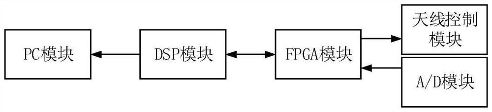
[0047] refer to figure 1 , the microwave correlation imaging device of the present invention will be further described in detail.

[0048] The microwave-related imaging device of the present invention includes an antenna control module, an A / D module, an FPGA module, a DSP module, and a PC display module, figure 1 The arrows in indicate the flow of data between modules.

[0049] The antenna control module is used to control the phased array antenna according to the received random phase encoding information;

[0050] The A / D input module is used for collecting the echo signal received by the receiving antenna in real time.

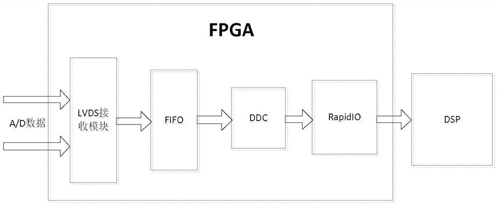
[0051] The FPGA module is used to perform digital down-conversion preprocessing on the echo signal collected by the A / D, and send an interrupt message to the DSP module while sending the baseband echo signal to...


PUM


Abstract

The invention discloses a real-time microwave correlated imaging device and method based on an FPGA and a DSP, and mainly solves the problems of long consumed time, incapability of real-time imagingand lack of a complete imaging device of a correlated imaging algorithm in the prior art. The device comprises an antenna control module, a DSP module, an A / D module, an FPGA module and a PC display module. The method comprises the steps of (1) generating and sending random phase encoding information; (2) generating an antenna radiation field which fluctuates randomly; (3) collecting data; (4) preprocessing and sending echo data; (5) acquiring a microwave associated super-resolution image; and (6) enabling the PC display module to display the microwave associated super-resolution image. According to the invention, the respective architecture characteristics of the FPGA and the DSP are fully utilized, the advantage of parallel execution and the processing speed of the multi-core DSP are exerted, and high accuracy is ensured on the premise of well meeting the real-time performance.

Description

technical field [0001] The present invention belongs to the technical field of radar communication, and further relates to a real-time microwave associated imaging device based on Field-Programmable Gate Array (FPGA) (Field-Programmable Gate Array) and digital signal processor DSP (Digital Signal Processing) in the field of radar imaging technology and method. The present invention can be used in forward-looking or staring scenes to perform real-time imaging processing on radar echo data to obtain super-resolution images of radar-associated imaging. Background technique [0002] Microwave correlation imaging technology is an improved imaging theory that combines microwave real-aperture imaging technology and quantum imaging theory. Microwave correlation imaging is to interact with the target by constructing a radiation field that changes randomly in two dimensions in time and space, and correlate the received scattered echo with the radiation field, so as to realize high-re...

Claims


Application Information

Patent Timeline
Patent Type & Authority Applications(China)
IPC IPC(8): G01S13/90
CPCG01S13/9021G01S13/9004G01S13/9043G01S13/9094
Inventor 李亚超王健张浩黄平平阮峰全英汇吕金虎胡浩
Owner XIDIAN UNIV
Why Eureka
Try Eureka