Flue gas dust removal system

A dust removal system and flue gas technology, which is applied in the use of liquid separation agents, lighting and heating equipment, and dispersed particle separation, can solve the problems of large-scale flue gas cooling, cumbersome dust removal operations, and poor effects. Simple, low cost, good effect

Inactive Publication Date: 2020-11-10
ANHUI GUONENG YISHENG ENVIRONMENTAL PROTECTION SCI & TECH
View PDF9 Cites 0 Cited by
  • Summary
  • Abstract
  • Description
  • Claims
  • Application Information

AI Technical Summary

Problems solved by technology

[0002] When the garbage is burned, high-temperature flue gas will be produced. If this flue gas is discharged directly into the air, on the one hand, the temperature of the flue gas will increase the excessive heat load on the environment; on the other hand, the acid gas of the flue gas will destroy the air composition points, resulting in adverse natural environmental reactions such as acid rain. With the development of waste treatment technology, incinerators integrating dust removal and purification have appeared. When processing high-temperature flue gas, this kind of furnace body will use water cooling or economizer and other measures to cool the flue gas, but the cost of this cooling method is very high, and it cannot meet the needs of large-scale flue gas cooling. It often happens that the temperature of the flue gas after cooling is still maintained above 90 degrees. The effect of using buffer solution to absorb gas under the conditions is very poor, and the dust removal operation after cooling is also very cumbersome. Therefore, we propose a flue gas dust removal system

Method used


Image

  • Flue gas dust removal system
  • Flue gas dust removal system
  • Flue gas dust removal system

Examples


Embodiment Construction

[0020] The following will clearly and completely describe the technical solutions in the embodiments of the present invention with reference to the accompanying drawings in the embodiments of the present invention. Obviously, the described embodiments are only some, not all, embodiments of the present invention. Based on the embodiments of the present invention, all other embodiments obtained by persons of ordinary skill in the art without making creative efforts belong to the protection scope of the present invention.

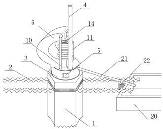
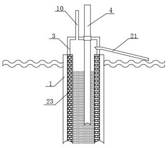
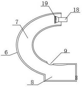
[0021] Such as Figure 1-4 As shown, a flue gas dedusting system includes a cooling well 1 and a flue gas delivery pipe 4. The cooling well 1 is located above the foundation 2 and extends upward. The upper end of the cooling well 1 is communicated with a transition chamber 3. The flue gas delivery pipe 4 passes The transition chamber 3 extends into the cooling well 1, the outer surface of the transition chamber 3 is provided with an observation window 5, and t...


PUM


Abstract

The invention discloses a flue gas dust removal system, which comprises a cooling well and a flue gas conveying pipe; the cooling well is located above a foundation and extends upwards, wherein the upper end of the cooling well is provided with a transition chamber in a communicating mode, the flue gas conveying pipe penetrates through the transition chamber and extends into the cooling well, andan observation window is arranged on the outer side face of the transition chamber; a smoke washing box is fixedly arranged at the upper end of the transition chamber and comprises a curved flow channel and a liquid collecting tank, and two sets of air guide pipes are symmetrically arranged at the upper end of the transition chamber and extend upwards to the two sides of the top of the smoke washing box. According to the flue gas dust removal system, by designing the cooling well, compared with traditional cooling structures such as a coal economizer and a water cooler, the cooling well utilizes underground water, so that the use cost is low, the contact time is greatly prolonged, the cooling effect on high-temperature flue gas is better, dust particles in the flue gas can be directly absorbed, and certain self-purification capacity is achieved. The system is suitable for large-scale operation, is suitable for different working conditions, and shows a better application prospect.

Description

technical field [0001] The invention relates to the field of flue gas treatment, in particular to a flue gas dust removal system. Background technique [0002] When the garbage is burned, high-temperature flue gas will be produced. If this flue gas is directly discharged into the air, on the one hand, the temperature of the flue gas will increase the excessive heat load on the environment; on the other hand, the acid gas of the flue gas will destroy the air composition points, resulting in adverse natural environmental reactions such as acid rain. With the development of waste treatment technology, incinerators integrating dust removal and purification have appeared. When processing high-temperature flue gas, this kind of furnace body will use water cooling or economizer and other measures to cool the flue gas, but the cost of this cooling method is very high, and it cannot meet the needs of large-scale flue gas cooling. It often happens that the temperature of the flue gas ...

Claims


Application Information

Patent Timeline
Patent Type & Authority Applications(China)
IPC IPC(8): B01D47/02B01D53/18F23J15/06
CPCB01D47/02B01D53/1456B01D53/18F23J15/06
Inventor 钟华张兵梁明
Owner ANHUI GUONENG YISHENG ENVIRONMENTAL PROTECTION SCI & TECH
Why Eureka
Try Eureka