Distributed optical fiber broadband stable-phase transmission system and method based on ring topology

A distributed optical fiber, phase-stable transmission technology, applied in optical fiber transmission, transmission system, electromagnetic wave transmission system, etc., can solve complex control, huge distributed transmission system, transmission frequency signal frequency/phase can not meet the user's high-precision requirements, etc. problems, to achieve the effect of improving performance and avoiding impact

Active Publication Date: 2020-11-10
THE 44TH INST OF CHINA ELECTRONICS TECH GROUP CORP +1
View PDF24 Cites 0 Cited by
  • Summary
  • Abstract
  • Description
  • Claims
  • Application Information

AI Technical Summary

Problems solved by technology

Optical fiber-based frequency transmission technology faces the problem that the transmission delay of the optical fiber link changes with factors such as temperature, stress, vibration, and transmission wavelength. The continuous deterioration of the frequency / phase of the transmission frequency signal cannot meet the high-precision requirements of users; in the distribution In the traditional frequency-phase stable transmission system, there is no guarantee that each user node can achieve phase synchronization / consistent frequency signal reception
[0003] For distributed frequency-stable transmission, a commonly used method is to operate multiple sets of point-to-point frequency-stable transmission systems independently, but as the number of distributed nodes increases, the entire distributed transmission system will become larger and larger, and the control will become more and more complicated

Method used


Image

  • Distributed optical fiber broadband stable-phase transmission system and method based on ring topology
  • Distributed optical fiber broadband stable-phase transmission system and method based on ring topology
  • Distributed optical fiber broadband stable-phase transmission system and method based on ring topology

Examples


Embodiment 1

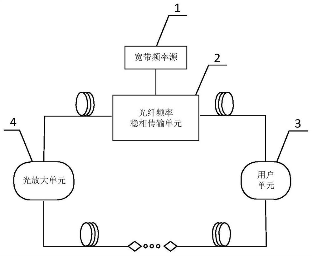
[0051] Such as figure 1 As shown, it is a schematic structural diagram of a preferred embodiment of the ring topology-based distributed optical fiber broadband phase-stable transmission system of the present invention. The transmission system includes a broadband frequency source 1, an optical fiber frequency phase-stable transmission unit 2, N user units 3 connected in series and M optical amplification units 4 connected in series, and the optical fiber frequency phase-stable transmission unit 2 has a first port , a second port and a third port, the output end of the broadband frequency source 1 is connected to the first port of the optical fiber frequency phase-stable transmission unit 2, and the second port of the optical fiber frequency phase-stable transmission unit 2 passes through N users in sequence The unit 3 and M optical amplification units 4 are connected to the third port of the fiber frequency phase-stable transmission unit 2 to form a single-fiber bidirectional ...

Embodiment 2

[0068] Such as Figure 4 As shown, it is a flow chart of the distributed optical fiber broadband phase-stable transmission method based on the ring topology of the present invention, which specifically includes the following steps:

[0069] In this embodiment, the wavelength of the broadband signal transmitted clockwise by the optical fiber frequency phase-stable transmission unit 2 is 1550.12 mm, the wavelength of the broadband signal transmitted counterclockwise is 1551.72 mm, and the broadband signal to be transmitted is 10 Any point frequency signal between ~18GHz.

[0070] S1: The broadband frequency source 1 transmits the broadband signal to the optical fiber frequency phase-stable transmission unit 2 .

[0071] S2: The optical fiber frequency phase-stable transmission unit 2 converts the broadband signal input by the broadband frequency source into an optical-carrying broadband signal. port input into the fiber optic loop.

[0072] In this embodiment, the point frequ...

Embodiment 3

[0108] Such as Figure 4 As shown, it is a flow chart of the distributed optical fiber broadband phase-stable transmission method based on the ring topology of the present invention, which specifically includes the following steps:

[0109] The difference between this embodiment and Embodiment 2 is that the broadband signal sent by the broadband frequency source in this embodiment is a pulse frequency sweep signal, and its working principle is the same as that of Embodiment 2. The difference is that the second embodiment implements broadband phase-stable transmission through phase measurement, and this embodiment implements broadband phase-stable transmission through delay measurement, and can realize phase synchronization of signals received by each user. In this embodiment, the wavelength of the fiber-optic broadband signal transmitted clockwise by the optical fiber frequency phase-stable transmission unit 2 is 1550.12 mm, and the wavelength of the optical broadband signal t...


PUM


Abstract

The invention discloses a distributed optical fiber broadband stable-phase transmission system and method based on ring topology, and the system comprises a broadband frequency source, an optical fiber frequency stable-phase transmission unit, N user units, and M optical amplification units. The optical fiber frequency stable-phase transmission unit is provided with a first port, a second port, and a third port. The output end of the broadband frequency source is connected with a first port of the optical fiber frequency stable-phase transmission unit, and a second port of the optical fiber frequency stable-phase transmission unit is connected with a third port of the optical fiber frequency stable-phase transmission unit through N user units and M optical amplification units in sequence to form a single-fiber bidirectional series annular topological path; while distributed optical fiber broadband stable-phase transmission is realized, the influence of environmental factors such as internal temperatures of different transmitting stations on an optoelectronic device can be avoided, and the defects of large size and complex control of a central station optical fiber frequency stable-phase transmission unit system along with increase of distributed nodes can also be effectively avoided.

Description

technical field [0001] The invention relates to the technical field of optical fiber broadband transmission, in particular to a distributed optical fiber broadband phase-stable transmission system and method based on a ring topology. Background technique [0002] High-precision frequency signals have important application value in the fields of satellite navigation, aerospace, deep space exploration, reconnaissance and early warning. Optical fiber transmission has the advantages of low loss, large capacity, large bandwidth, high speed, high stability, safety and reliability, and has been widely used in the communication field. Optical fiber-based frequency transmission technology is an effective way to achieve higher-precision frequency transmission and distribution, and continues to promote the development of microwave photonics related fields. Optical fiber-based frequency transmission technology faces the problem that the transmission delay of the optical fiber link chan...

Claims


Application Information

Patent Timeline
IPC IPC(8): H04B10/2575H04B10/25
CPCH04B10/25755
Inventor 张浩杨海峰田思玉孙力军
Owner THE 44TH INST OF CHINA ELECTRONICS TECH GROUP CORP
Why Eureka
Try Eureka