A kind of additive manufacturing method of gas-liquid two-phase heat exchanger

A technology of additive manufacturing and heat exchangers, which is applied in the direction of additive processing, process efficiency improvement, and energy efficiency improvement, which can solve the problems of material waste, heat transfer area smaller than material surface area, and failure to break through the bottleneck of heat exchange efficiency. Achieve excellent sealing performance, high heat transfer efficiency, and increase the effect of heat transfer area

Active Publication Date: 2021-10-08
TONGJI UNIV
View PDF11 Cites 0 Cited by
  • Summary
  • Abstract
  • Description
  • Claims
  • Application Information

AI Technical Summary

Problems solved by technology

The surface area of ​​the material in the gas-liquid heat exchanger is much larger than the heat exchange area, making it difficult to improve the utilization of heat exchange materials in the heat exchanger
[0005] In the existing gas-liquid heat exchange, most of the gas-liquid flow channels are designed independently of each other, that is, two independent fluid structure systems. Although the designer can increase the gas-liquid contact area by means of wave plates, the heat transfer area is always smaller than The surface area of ​​the material cannot make full use of the material, resulting in the waste of a large amount of material and the bottleneck of heat exchange efficiency that cannot be broken through.

Method used


Image

  • A kind of additive manufacturing method of gas-liquid two-phase heat exchanger
  • A kind of additive manufacturing method of gas-liquid two-phase heat exchanger
  • A kind of additive manufacturing method of gas-liquid two-phase heat exchanger

Examples


Embodiment 1

[0046] The additive manufacturing method of the gas-liquid two-phase heat exchanger in this embodiment includes the following steps:

[0047] S1: Set the parameters of the SLM metal printer, load the metal raw material powder, and load the 3D model of the gas-liquid two-phase heat exchanger.

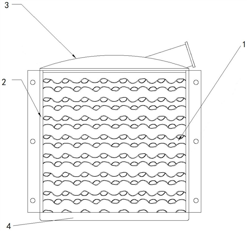
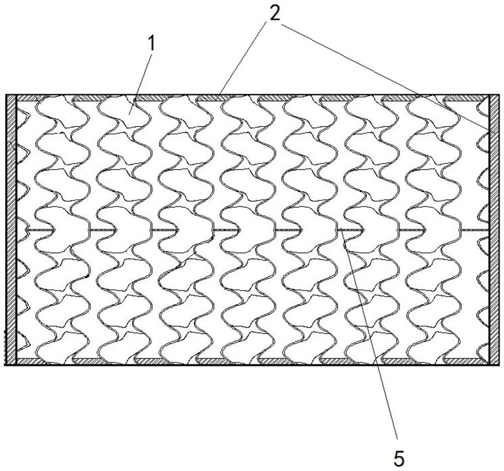
[0048] The 3D model used in this embodiment includes the models of the bottom plate, the cover core 1, the sealing wall 2, the drainage assembly 3, and the deflector assembly 4, see figure 1 and figure 2 , wherein the gas channel and the liquid channel in the model of the core body 1 are both 3D spiral channel structures, and the extension length directions of the 3D spiral channels corresponding to the gas channel and the liquid channel are perpendicular to each other, forming a partition heat exchange structure, The parameters of the SLM printer are set as follows: the printing size accuracy is ±0.05mm, the scanning speed is 100mm / s-1000mm / s, and the laser power is set to 130W-400W,...

Embodiment 2

[0068] Different from Example 1, the powder bed molten metal printer in this Example S1 is an SLS printer, and the parameters of the SLS printer are set as follows: the scanning speed is 100mm / s-400mm / s, and the laser power is set to 50W-150W, so that the printed material The density is more than 95% of the metal density used.


PUM

PropertyMeasurementUnit
tensile strengthaaaaaaaaaa

Abstract

The invention relates to a method for additive manufacturing of a gas-liquid two-phase heat exchanger, comprising S1: setting the parameters of a powder bed molten metal printer, loading metal raw material powder, loading the 3D model of the gas-liquid two-phase heat exchanger, and printing The density of the output material is more than 95% of the density of the metal used. S2: Print out the bottom plate and baffle components of the gas-liquid two-phase heat exchanger; S3: Print out the sealing wall and the core inside the sealing wall; S4: Print out the cover and the drainage component inside the cover. S5: After printing layer by layer from bottom to top, perform annealing treatment to eliminate thermal stress in the product. After annealing treatment, perform etching or polishing to obtain a finished gas-liquid two-phase heat exchanger. Compared with the prior art, the invention breaks the technical bottleneck of the traditional heat exchanger processing process, the heat transfer area is approximately equal to the material surface area, the material utilization rate is increased to nearly 100%, and the heat exchange area is significantly increased.

Description

technical field [0001] The invention relates to the field of heat exchangers, in particular to an additive manufacturing method for a gas-liquid two-phase heat exchanger. Background technique [0002] Gas-liquid heat exchangers are widely used in industrial production processes, and their functions include gas or liquid preheating and heating, liquid or gas residual heat recovery, etc. Gas-liquid heat exchangers include double-tube, shell-and-tube, and plate frame structures. [0003] At present, although there are various types of heat exchangers commonly used in the market, most of them have similar structures. Due to the requirements of industrial production, most parts need to be produced separately, and the method of subtractive manufacturing is required, which leads to complex issues such as the difficulty of sealing and production of equipment parts. [0004] CN102012175B discloses a new type of gas-liquid heat exchange device, which includes a main heat exchange pl...

Claims


Application Information

Patent Timeline
Patent Type & Authority Patents(China)
IPC IPC(8): B22F3/105B33Y10/00B33Y50/02
CPCB33Y10/00B33Y50/02Y02P10/25
Inventor 严鹏飞尹泽诚严彪
Owner TONGJI UNIV
Why Eureka
Try Eureka