A heat storage reversing flameless combustion device

A flameless combustion and heat storage technology, applied in the direction of burners, combustion types, combustion methods, etc., can solve problems such as incomplete combustion of burners, many production failures, uneven heating temperature, etc., and achieve reduction of nitrogen oxide emissions, Improve the effect of high combustion efficiency and uniform heating temperature

Active Publication Date: 2022-07-12
武汉钢铁有限公司
View PDF10 Cites 0 Cited by
  • Summary
  • Abstract
  • Description
  • Claims
  • Application Information

AI Technical Summary

Problems solved by technology

[0004] Since the burner of the current regenerative burner is responsible for combustion and smoke exhaust at the same time, and the nozzle of the burner is also a smoke exhaust port, it is difficult to achieve flameless low-nitrogen combustion and high-efficiency heat storage and energy saving at the same time with the same fixed nozzle. The nozzle also has many problems such as incomplete combustion of the burner, uneven heating temperature, poor smoke exhaust, high furnace pressure, insufficient heat storage and heat exchange, low energy saving effect, easy damage to equipment, and many production failures.

Method used


Image

  • A heat storage reversing flameless combustion device
  • A heat storage reversing flameless combustion device
  • A heat storage reversing flameless combustion device

Examples


Embodiment 1

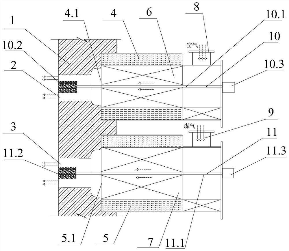
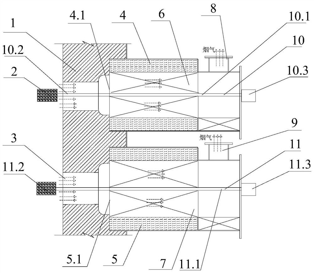
[0038] combine figure 1 and figure 2 As shown, the regenerative reversing flameless combustion device of this embodiment is a blast furnace gas double regenerative type, which specifically includes a burner brick 1, an air nozzle 2, a gas nozzle 3, an air thermal storage tank 4, a gas thermal storage tank 5, Air heat accumulator 6, gas heat accumulator 7, air pipe 8, gas pipe 9, first telescopic mechanism 10, first stretch rod 10.1, first plug 10.2, first two-position telescopic valve head 10.3, second The telescopic mechanism 11, the second stretch rod 11.1, the second plug 11.2, and the second two-position telescopic valve head 11.3.

[0039] The burner brick 1 is provided with two nozzles, the two nozzles are the air nozzle 2 and the gas nozzle 3 respectively. The air nozzle 2 and the gas nozzle 3 are arranged up and down along the height direction of the burner brick 1 .

[0040] An air heat storage chamber 4.1 is set up in the air heat storage box 4 along its axial dir...

Embodiment 2

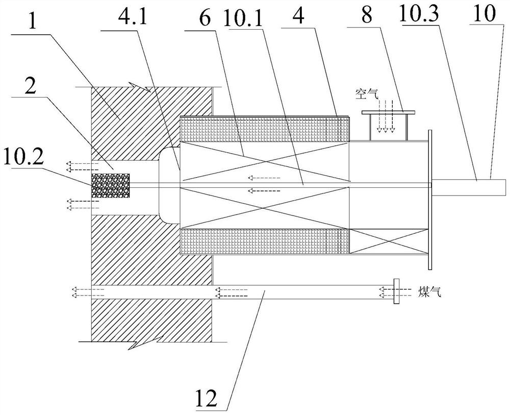
[0047] combine image 3 and Figure 4 As shown, the regenerative reversing flameless combustion device of this embodiment is a single regenerative type of coke oven gas, which specifically includes a burner brick 1, an air nozzle 2, an air regenerator box 4, an air regenerator 6, and an air pipe 8. , The first telescopic mechanism 10 , the first stretching rod 10.1 , the first plug 10.2 , the first two-position telescopic valve head 10.3 , and the first gas straight-through pipe 12 .

[0048] The air nozzle 2 is opened on the upper part of the burner brick 1, the air nozzle 2 extends inward along the outer end surface of the burner brick 1, and the first gas straight pipe 12 is arranged at the lower part of the burner brick 1, along the outer end of the burner brick 1 The face extends inward until it runs through the entire burner block 1 .

[0049] The air heat storage box 4 is provided with an air heat storage chamber 4.1 along its axial direction; an air heat storage body...

Embodiment 3

[0052] combine Figure 5 and Image 6 As shown, the regenerative reversing flameless combustion device in this embodiment is a natural gas single regenerative type, which specifically includes a burner brick 1, an air nozzle 2, an air regenerator 4, an air regenerator 6, an air pipe 8, a A telescopic mechanism 10 , a first stretch rod 10.1 , a first plug 10.2 , a first two-position telescopic valve head 10.3 , and a second gas straight-through pipe 14 .

[0053] The burner brick 1 is provided with an air nozzle 2, the air nozzle 2 extends inward along the outer end face of the burner brick 1, and an air heat storage chamber 4.1 is opened in the air heat storage box 4 along its axial direction; in the air heat storage chamber 4.1 An air heat storage body 6 is installed inside; the air nozzle 2, the air heat storage cavity 4.1 and the air pipe 8 are connected in sequence to form an air circulation passage.

[0054] The second gas straight pipe 14 penetrates through the air cir...


PUM


Abstract

The invention relates to the field of regenerative burners, in particular to a regenerative reversing flameless combustion device. The heat storage reversing flameless combustion device of the present invention includes an air circulation passage, a gas circulation passage and an air heat storage body arranged in the air circulation passage, and also includes a first telescopic mechanism, and the first telescopic mechanism includes a first stretching mechanism. The rod, the first plug and the first and second position telescopic valve heads. The first stretch rod penetrates into the air circulation passage. One end of the first stretch rod is connected with the first and second position telescopic valve heads. The other end is connected with the first plug; when the first and second position telescopic valve heads are in the burning position, the first plug is located in the air nozzle, and when the first and second position telescopic valve heads are switched to the smoke exhaust position, the first and second position telescopic valve heads are in the burning position. The head pushes the first stretch rod in the direction of air outflow until the entire first plug is located outside the air vent. The invention adjusts the size of the nozzle of the burner through the telescopic mechanism, so as to realize the high-speed jet flow from the small nozzle and the rapid exhaust smoke from the large nozzle.

Description

technical field [0001] The invention relates to the field of regenerative burners, in particular to a regenerative reversing flameless combustion device. Background technique [0002] Flameless combustion is a new type of high-efficiency and low-polluting combustion technology that can reduce nitrogen oxide emissions by 70%. It is regarded by the international combustion community as one of the most promising technologies in the 21st century. In flameless combustion, high-speed jets are used to entangle the smoke, dilute the combustion medium, and form a lean-oxygen combustion condition. High-speed jets are the main way to form flameless combustion. The regenerative burner is a high-efficiency and energy-saving combustion device. By setting a regenerative body in the burner and performing periodic reversal through a reversing valve, the regenerative body in the burner continuously stores and releases heat, which can reduce the high temperature. The flue gas is subjected to ...

Claims


Application Information

Patent Timeline
Patent Type & Authority Patents(China)
IPC IPC(8): F23D14/22F23D14/46F23D14/66
CPCF23D14/22F23D14/46F23D14/66Y02E20/34
Inventor 丁翠娇曹炳雷朱善合向云畔陈超
Owner 武汉钢铁有限公司
Why Eureka
Try Eureka