
Negative pole piece with coating layer as well as preparation method and application of negative pole piece

A negative pole piece and coating technology, which is applied in the field of high-energy-density all-solid-state batteries, can solve the problems of reducing the transmission efficiency of lithium metal and sulfide ions, large changes in electrode volume, and failure of all-solid-state batteries. energy, increase energy density, and improve electrochemical performance

Active Publication Date: 2020-11-13
中科(马鞍山)新材料科创园有限公司 +1
View PDF24 Cites 2 Cited by
  • Summary
  • Abstract
  • Description
  • Claims
  • Application Information

AI Technical Summary

Problems solved by technology

[0004] However, using lithium metal as the negative electrode of an all-solid-state battery has a large change in electrode volume during the cycle, which will lead to electrode pulverization failure in severe cases, and a significant drop in cycle performance. At the same time, lithium is an active material in the electrode, and the corresponding safety hazards are relatively large. For this reason, some manufacturers of all-solid-state batteries have considered using lithium metal and sulfide together to further improve the performance of all-solid-state batteries.
Due to the relationship between the chemical properties of lithium metal and sulfide itself, direct contact between the two is easy to react, resulting in the formation of a stable substance on the surface of lithium metal that blocks the contact between lithium metal and sulfide, thereby reducing the ion density between lithium metal and sulfide. The transmission efficiency will increase the internal resistance of the battery over time, which will cause the all-solid-state battery to fail

Method used


Image

  • Negative pole piece with coating layer as well as preparation method and application of negative pole piece
  • Negative pole piece with coating layer as well as preparation method and application of negative pole piece

Examples


Embodiment 1

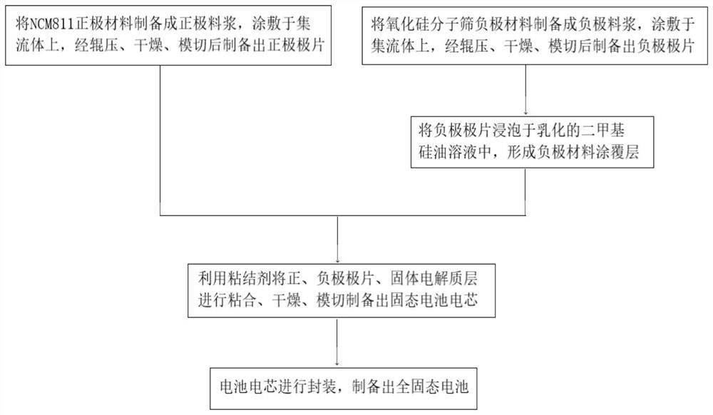
[0066] This embodiment provides a negative electrode sheet with a coating layer and a preparation method thereof. The negative electrode sheet includes a negative electrode current collector, and a negative electrode material layer and a coating layer sequentially located on both sides of the negative electrode current collector. The thickness of the layer is 20 μm.

[0067] The preparation method of the negative pole piece comprises the following steps:

[0068] Select silicon oxide molecular sieve as the negative electrode material with a porosity of 30%. Mix the negative electrode material and the conductive agent (SFG-6) evenly, and then mix them with the binder (SBR). The amount of the binder added is the mass of the negative electrode mixture %, the amount of conductive agent added is 5% of the mass of the negative electrode mixture material, mixed to prepare negative electrode slurry, coated on 12μm copper foil, moved to a vacuum oven with a vacuum degree of 0.6Mpa, vac...

Embodiment 2

[0075] This embodiment provides a negative electrode sheet with a coating layer and a preparation method thereof. The negative electrode sheet includes a negative electrode current collector, and a negative electrode material layer and a coating layer sequentially located on both sides of the negative electrode current collector. The thickness of the layer was 22 μm.

[0076] The preparation method of the negative pole piece comprises the following steps:

[0077] Select silicon oxide molecular sieve as the negative electrode material with a porosity of 28%. Mix the negative electrode material and conductive agent (SFG-6) evenly, and then mix them with the binder (SBR). The amount of binder added is the mass of the negative electrode mixture material 2 %, the amount of conductive agent added is 5% of the mass of the negative electrode mixture material, mixed to prepare negative electrode slurry, coated on 12μm copper foil, moved to a vacuum oven with a vacuum degree of 0.7Mpa,...

Embodiment 3

[0083] This embodiment provides a negative electrode sheet with a coating layer and a preparation method thereof. The negative electrode sheet includes a negative electrode current collector, and a negative electrode material layer and a coating layer sequentially located on both sides of the negative electrode current collector. The thickness of the layer was 23 μm.

[0084] The preparation method of the negative pole piece comprises the following steps:

[0085] Select silicon oxide molecular sieve as the negative electrode material with a porosity of 25%. Mix the negative electrode material and conductive agent (SFG-6) evenly, and then mix them with the binder (SBR). The amount of binder added is the mass of the negative electrode mixture material 2 %, the amount of conductive agent added is 5% of the mass of the negative electrode mixture material, mixed to prepare negative electrode slurry, coated on a 12 μm copper foil, moved to a vacuum oven with a vacuum degree of 0.4M...


PUM

PropertyMeasurementUnit
thicknessaaaaaaaaaa
thicknessaaaaaaaaaa
thicknessaaaaaaaaaa

Abstract

The invention discloses a negative pole piece with a coating layer as well as a preparation method and application of the negative pole piece. The negative pole piece comprises a negative current collector, and a negative material layer and the coating layer which are sequentially positioned on the surface of at least one side of the negative current collector, wherein a negative active substancein the negative material layer comprises a silicon oxide molecular sieve, and the coating layer comprises simethicone and lithium salt. According to the invention, the negative electrode material replaces the use of lithium metal by adopting the silicon oxide molecular sieve, the silicon oxide molecular sieve is a porous silicon material, the negative pole piece material is prepared from the material, and the surface of the negative pole piece material is coated with the coating layer made of a special material, so that the internal resistance can be effectively reduced, and the battery performance is improved. Meanwhile, the positive electrode is prepared from a high-nickel ternary nickel-cobalt-manganese material, so that the performance of the solid-state battery can be further improved, and the high-energy-density all-solid-state battery can be obtained.

Description

technical field [0001] The present invention relates to the field of new energy power batteries, in particular to the technical field of all-solid-state batteries, to a negative pole piece with a coating layer, its preparation method and application, in particular to a negative pole piece with a coating layer, its preparation Methods, solid-state battery cells and all-solid-state batteries with high energy density. Background technique [0002] The traditional liquid lithium battery is also vividly called "rocking chair battery" by scientists. The two ends of the rocking chair are the positive and negative poles of the battery, and the electrolyte (liquid) is in the middle. Lithium ions are like excellent athletes, running back and forth at both ends of the rocking chair. During the movement of lithium ions from the positive electrode to the negative electrode and then to the positive electrode, the charging and discharging process of the battery is completed. [0003] The ...

Claims


Application Information

Patent Timeline
Patent Type & Authority Applications(China)
IPC IPC(8): H01M4/485H01M4/131H01M4/1391H01M4/62H01M10/0525
CPCH01M4/485H01M4/625H01M4/626H01M4/131H01M4/1391H01M10/0525H01M2004/027Y02E60/10
Inventor 冯海兰冯建林谭强强
Owner 中科(马鞍山)新材料科创园有限公司
Learn More