Microbe alternate grouting device for soft soil stabilization and using method

A grouting device and microbial technology, applied in construction, infrastructure engineering, etc., can solve the problem that bacteria liquid and cement solution cannot achieve the reinforcement effect

Active Publication Date: 2020-11-17
SOUTHWEST PETROLEUM UNIV
View PDF11 Cites 2 Cited by
  • Summary
  • Abstract
  • Description
  • Claims
  • Application Information

AI Technical Summary

Problems solved by technology

[0004] The object of the present invention is to provide a microbial alternate grouting device and method for solidifying soft soil, which solves the problem that the presence of po...

Method used


Image

  • Microbe alternate grouting device for soft soil stabilization and using method
  • Microbe alternate grouting device for soft soil stabilization and using method
  • Microbe alternate grouting device for soft soil stabilization and using method

Examples


Embodiment 1

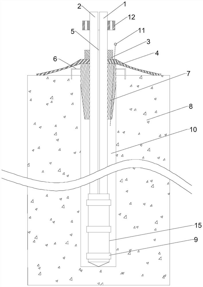
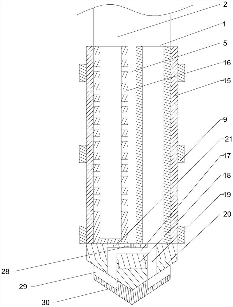
[0050] Such as Figure 1~5 As shown, this embodiment includes a suction pipe 2 with both ends closed, and a plurality of suction holes 16 are opened on the outer peripheral wall of the lower section along the circumferential direction of the suction pipe 2, and also includes a 2 The grouting pipe 1 parallel to the axis, the grouting pipe 1 and the suction pipe 2 are connected to form a solidification pipeline through the partition 5, and the lower end surface of the partition 5, the lower end surface of the grouting pipe 1 and the suction pipe 2 The end faces are flush, and the outer wall of the upper section of the curing pipeline is sequentially set with nuts 3, spacers 4 and stoppers 7, and the outer wall of the lower section of the curing pipeline is wrapped with non-woven fabrics 15 and stoppers. 7 The outer diameter is the same as the inner diameter of the grouting hole 10; the upper end of the grouting pipe 1 is connected with the slurry tank, the upper end of the sucti...

Embodiment 2

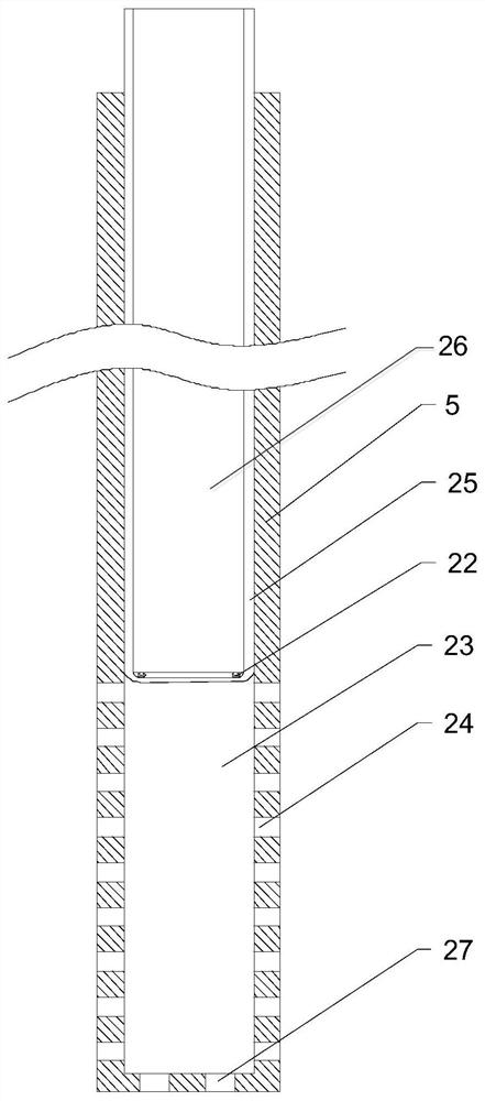
[0055] Such as figure 1 , 4 , 5, this embodiment is based on the embodiment, a cavity 23 is opened in the middle of the partition plate 5, and the upper end of the cavity 23 is open, and a matching follower is provided slidingly in the cavity 23. Plate 26, two transmission rollers 22 are arranged on the lower end face of described follow-up plate 26, are covered with waterproof membrane 25 on two transmission rollers 22, and the two ends of waterproof membrane 25 are along the two sides of follow-up plate 26 respectively. The two side walls extend upwards to the open end protruding from the cavity 23, and a plurality of filter holes 24 are arranged on the lower sections of the two inner side walls of the partition 5 facing the waterproof membrane 25, and a plurality of filter holes 24 are opened at the bottom of the partition 5. There are a plurality of bottom holes 27 , and a plurality of butt holes 28 aligned with the bottom holes 27 are opened on the upper surface of the j...

Embodiment 3

[0060] Such as Figure 1~6 As shown, this embodiment includes the following steps:

[0061] Including the following steps:

[0062] S 1 1. Excavate the side ditch 34, the depth of the side ditch is K, lay geotextiles in the side ditch 34 and the grouting area, and then lay the vacuum film 38 for sealing;

[0063] S 2 . Divide multiple grouting devices into two groups. One group is numbered as grouting device I and the other group is numbered as grouting device II. Insert the soil body 8 in sequence according to the depth values ​​H and L, and the one with the insertion depth value H is the grouting device. Grouting device I, the insertion depth value L is the grouting device II, and H

[0064] S 3 , Drainage pipes 35 are arranged on both sides of the side ditch 34;

[0065] S 4 , Start the vacuum pump 40 connected to the grouting device I and grouting device II until the vacuum under the membrane reaches 80KPa, and then keep the pressure stable within a week;

[006...


PUM


Abstract

The invention discloses a microbe alternate grouting device for soft soil stabilization and a using method. The microbe alternate grouting device comprises an air suction pipe, wherein a plurality ofair suction holes are formed in the outer wall of the air suction pipe; a grouting pipe and the air suction pipe are connected into one stabilization pipeline through a partition plate, and the outerwall of the lower section of the stabilization pipeline is wrapped with non-woven fabric; the upper end of the grouting pipe communicates with a slurry tank, and the upper end of the air suction pipeis connected with a water-air separator and a vacuum pump; and a connector is arranged at the lower end of the stabilization pipeline, a flow channel is arranged in the middle part of the connector, and a downward pressing block is connected to the lower end of the connector and provided with a plurality of slurry spraying channels. Alternate grouting is carried out through the grouting device, large-area grouting stabilization of soil mass can be rapidly achieved while the slurry using amount is greatly reduced, the grouting device starts the vacuum pump at the same time after grouting stabilization of the soil mass is completed, high-concentration NH4Cl generated through a reaction is pumped out and loaded into a specific container to be conveyed to a sewage treatment plant to be treated, and therefore soil and underground water can be prevented from being polluted.

Description

technical field [0001] The invention relates to the technical field of solidification and anti-seepage in soil engineering, and specifically provides a microbial solidification device that adopts a vacuum grouting process and is applicable to geotechnical engineering soil. Background technique [0002] In recent years, with the gradual rise of microbial-induced calcium carbonate precipitation (MICP) technology, microbial-induced soil stabilization has become a research hotspot in engineering soil reinforcement due to its unique advantages of low-energy perturbation and ecological environmental protection. At present, the mainstream method of MICP is the urease produced by Bacillus busus to induce the hydrolysis of urea. The reason is that the mechanism of this method is simple, the reaction process is easy to control, and a large amount of CaCO can be produced in a short time. 3 . The specific operation is to pour bacteria solution and cement solution (urea and CaCl) into t...

Claims


Application Information

Patent Timeline
IPC IPC(8): E02D15/02
CPCE02D15/02E02D2250/003E02D2250/0053
Inventor 郭亮郭豪彭颐祈王银帅戴启辰刘丰威李佳艺何肖玉廖明伟阿布拉铁张军伟
Owner SOUTHWEST PETROLEUM UNIV
Why Eureka
Try Eureka