
Blood purification device

A blood purification and blood chamber technology, applied in the field of medical devices, can solve problems such as limited contact area, membrane rupture, and dialyzer incompatibility, and achieve the effect of increasing the contact area and avoiding membrane rupture

Inactive Publication Date: 2020-11-20
山东省立第三医院
View PDF0 Cites 0 Cited by
  • Summary
  • Abstract
  • Description
  • Claims
  • Application Information

AI Technical Summary

Problems solved by technology

[0004] The first, existing dialyzer has certain limitation when using, and the dialysis membrane tube in the existing dialyzer may work for a long time (because the patient's dialysis treatment needs several hours to tens of hours according to the specific condition, so The doctor needs to replace the patient with a new dialyzer every specified time) or the pressure on the membrane is high, which leads to the occurrence of membrane rupture. Once membrane rupture occurs, the dialysis treatment must be suspended immediately to prevent the blood from being contaminated by the dialysate into the patient;
[0005] Second, the patient's body may not adapt to the dialyzer. The dialysis membrane tube in the existing dialyzer is made of textile or polymer materials, and the dialysis membrane tube as a foreign body can cause a series of reactions in the patient It includes two aspects: one is the blood-membrane reaction, and the anaphylactic toxin is released after the membrane body is activated, resulting in a series of clinical and subclinical manifestations; directly produce toxic effects;
[0006] Third, the contact area between the blood and the dialysate in the existing dialyzer is relatively limited, usually only the outside of the blood in the dialysis membrane tube is in contact with the dialysate

Method used


Image

  • Blood purification device
  • Blood purification device
  • Blood purification device

Examples


Embodiment

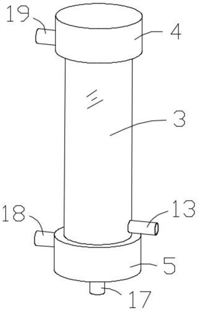
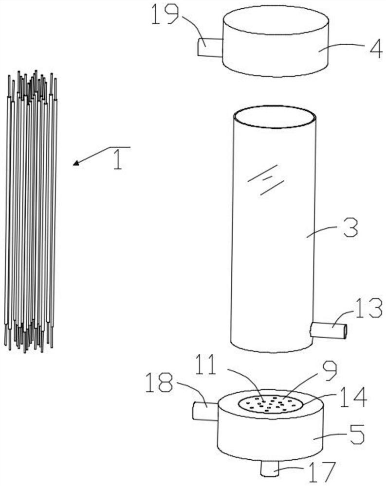
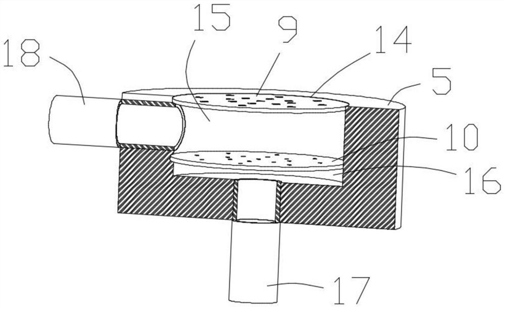
[0039] A kind of blood purification device of this embodiment, refer to Figure 1-12 : Including a set of filter assembly 1, positioning assembly 2, dialysis tube 3, upper tube cover 4 and lower tube cover 5; filter assembly 1 includes an outer tube 6 and an inner tube 7 pierced in the outer tube 6, and the outer tube 6 and Permeation holes 8 are opened on the body of the inner tube 7; the positioning assembly 2 includes a first circular plate 9 and a second circular plate 10 of the same size, and the first circular plate 9 is evenly opened with a second circular plate that matches the outer tube 6; A through groove 11, the second circular plate 10 is uniformly provided with a second through groove 12 matching the inner tube 7, and the number of the first through groove 11, the second through groove 12 and the filter assembly 1 are the same; the dialysis tube 3 A liquid inlet pipe 13 is provided on the tube body near one end of the lower tube cover 5; the surfaces of the upper...


PUM


Abstract

The invention relates to the technical field of medical instruments, in particular to a blood purification device. The device comprises a group of filtering assemblies, a positioning assembly, a dialysis tube, an upper tube cover and a lower tube cover, each filtering assembly comprises an outer pipe and an inner pipe connected into the outer pipe in a penetrating mode, the positioning assembly comprises a first circular plate and a second circular plate, a liquid inlet tube is arranged on the tube body at one end of the dialysis tube close to the lower tube cover, grooves are formed in the surfaces of the upper tube cover and the lower tube cover, a cavity between the first circular plate and the second circular plate in each groove is a blood chamber, a cavity between the second circularplate and the bottom of each groove in each groove is a liquid chamber, a liquid outlet pipe and a blood outlet pipe are arranged on the lower tube cover, a blood inlet pipe is arranged on the uppertube cover, and a group of flow guide grooves are formed in the upper tube cover and communicate the interior of the dialysis tube with the liquid chamber of the upper tube cover. According to the device, the membrane rupture phenomenon can be effectively avoided, and meanwhile the contact area of blood and dialyzate in a dialyzer can be effectively increased, and the affinity to the body of a patient can be effectively improved.

Description

technical field [0001] The invention relates to the technical field of medical devices, in particular to a blood purification device. Background technique [0002] Blood purification is also called dialysis in daily life. Its meaning is: lead the patient's blood out of the body and pass it through a purification device to remove some pathogenic substances, purify the blood, and achieve the purpose of treating diseases. Blood purification should include: hemodialysis, hemofiltration, hemoperfusion, plasma exchange, immunoadsorption, etc. Although peritoneal dialysis does not draw blood out of the body, the principles are the same. Hemodialysis is just one of the ways to treat chronic renal failure. Among them, the dialyzer is the core medical device in the process of blood purification treatment. [0003] However, the existing dialyzers have the following deficiencies in use: [0004] The first, existing dialyzer has certain limitation when using, and the dialysis membra...

Claims


Application Information

Patent Timeline
IPC IPC(8): A61M1/36A61M1/38
CPCA61M1/3621A61M1/38A61M1/3635A61M1/3661
Inventor 高一凯张莉
Owner 山东省立第三医院
Learn More