3D printing system of coaxial spiral structure reinforced composite material and machining method

A technology for reinforcing composite materials and helical structures, applied in the field of additive manufacturing, can solve problems such as inability to apply engineering, design means and manufacturing process limitations, and achieve the effect of improving compressive and flexural properties and huge application potential.

Pending Publication Date: 2020-11-20
JILIN UNIV
View PDF0 Cites 9 Cited by
  • Summary
  • Abstract
  • Description
  • Claims
  • Application Information

AI Technical Summary

Problems solved by technology

[0004] In the existing technology, even though the natural coaxial spiral structure materials provide new ideas for the design of new materials, they are limited by design methods and manufacturing processes, resulting in a long-term development of material structure innovation and manufacturing technology oriented to the synergistic optimization of compressive and bending properties. In the exploratory stage, practical engineering applications cannot be carried out

Method used


Image

  • 3D printing system of coaxial spiral structure reinforced composite material and machining method
  • 3D printing system of coaxial spiral structure reinforced composite material and machining method
  • 3D printing system of coaxial spiral structure reinforced composite material and machining method

Examples


no. 1 example 1

[0145] A more preferred first embodiment related to the method of the present application is as follows:

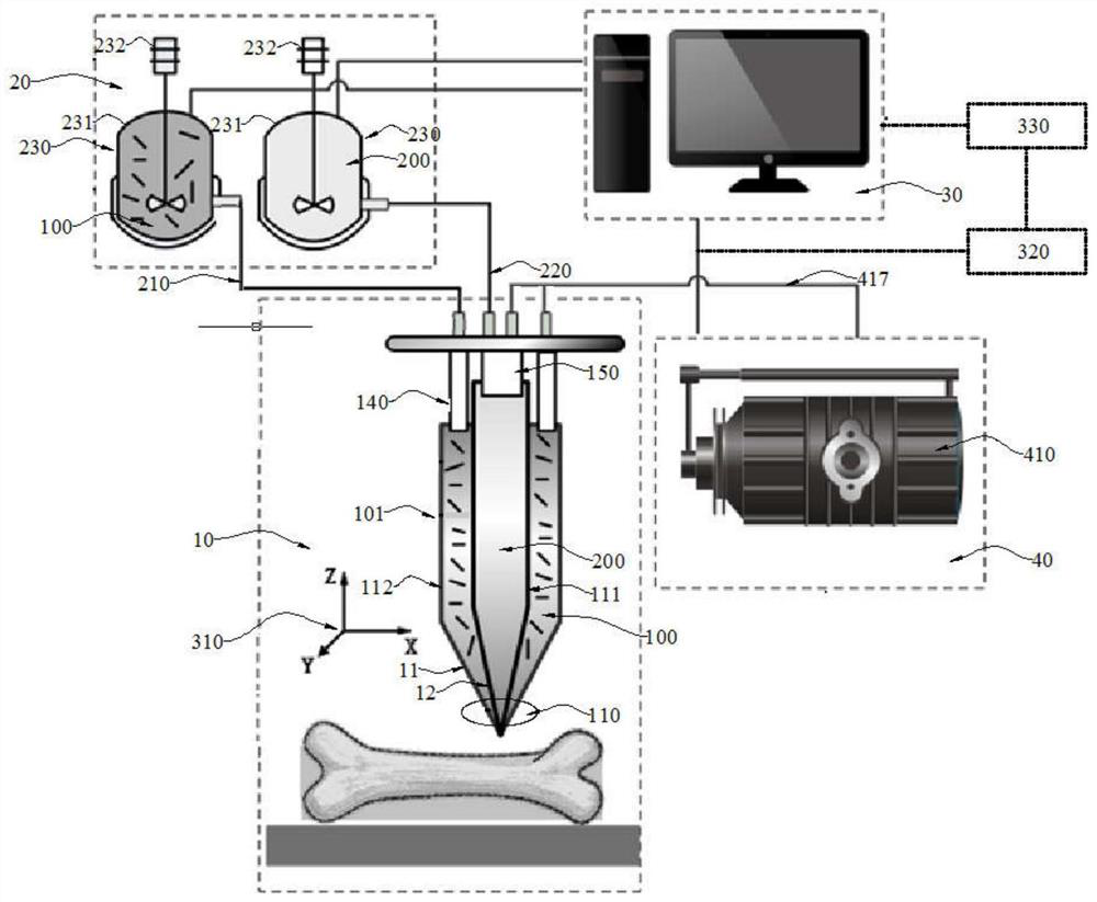
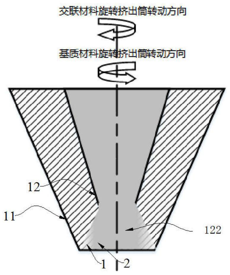
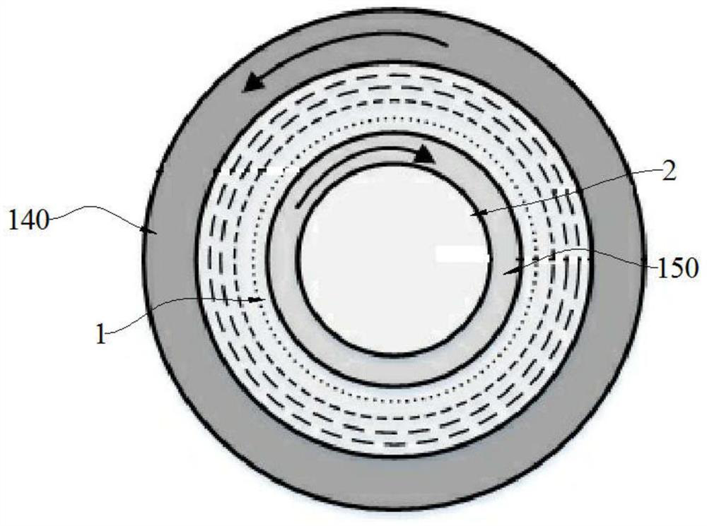
[0146] Preparation of cross-linked material: dissolving 2wt.% calcium chloride powder in 98wt.% deionized water to prepare calcium chloride solution; preparation of sodium alginate solution: 5wt.% sodium alginate powder and 1.5wt. % fumed silica was dissolved in 93.5wt.% deionized water to prepare sodium alginate solution; matrix material preparation: 50wt.% Al2O3 ceramic powder and 5wt.% SiC whiskers were added to 45wt.% alginic acid three times Sodium solution, stirred evenly, degassed in vacuum for 2 hours, set aside;

[0147] According to the pre-defined geometric model of compressive and flexural biomimetic composite materials and the distribution mode of internal coaxial helical structure fibers, a relevant three-dimensional model is established, and then the model is discretized;

[0148] According to the structural parameters of the characteristic structure in th...

no. 2 example 1

[0153] A preferred second embodiment related to the method of the present application is as follows:

[0154] Material preparation Preparation of cross-linked materials: Dissolving 3wt.% calcium chloride powder in 97wt.% deionized water to prepare calcium chloride solution; preparation of sodium alginate solution: dissolving 5wt.% sodium alginate powder and 1.5 wt.% fumed silica was dissolved in 93.5wt.% deionized water to prepare sodium alginate solution; preparation of matrix material: 60wt.% ceramic powder composed of Al2O3 and Si3N4 and 5wt.% made of carbon fiber and SiC crystal The reinforcing phase material composed of whiskers was added to the 35wt.% sodium alginate solution in three times, stirred evenly and then vacuum degassed for 2 hours, and set aside;

[0155] According to the pre-defined geometric model of compressive and flexural biomimetic composite materials and the distribution mode of internal coaxial helical structure fibers, a relevant three-dimensional mo...


PUM


Abstract

The invention relates to the technical field of additive manufacturing, in particular to a 3D printing system of a coaxial spiral structure reinforced composite material and a machining method. The 3Dprinting system of the coaxial spiral structure reinforced composite material and the machining method aim at solving the problems of compression resistance stability and bending resistance of an engineering supporting part, specifically, the system part comprises a three-dimensional forming manufacturing module, a computer control module and a controllable air pressure output system, wherein thethree-dimensional forming manufacturing module is used for outputting a matrix material and a cross-linking material according to two different preset rotation directions, so that the matrix materialand the cross-linking material construct a first printing body and a second printing body which are coaxial and are integrally formed; and the method comprises the following steps of material preparation, configuration of the matrix material and the cross-linking material in a programming material feeding module, coaxial spiral structure additive manufacturing and post-processing. Coaxial spiralarrangement of reinforcing phase discontinuous fibers in a composite material can be achieved, the compression resistance and the bending resistance of a reinforcing material are further reinforced ina coordinated mode, and the application range of engineering application is widened.

Description

technical field [0001] The invention relates to the technical field of additive manufacturing, in particular to a 3D printing system and a processing method of a coaxial spiral structure reinforced composite material. Background technique [0002] Under the current trend, the key requirements for supporting structures in the field of infrastructure facilities such as wind power generation systems and building unit systems include: First, the key parts of the system components need to be resistant to compression in terms of structure and material selection and stability; second, system components need to have anti-bending characteristics within a predetermined range; and the existing support structures are often difficult to effectively meet the above requirements, which can be summarized as: unable to effectively cope with complex load environments. [0003] In contrast, in nature, biological materials and tissue structures effectively solve this contradictory problem, and c...

Claims


Application Information

Patent Timeline
Patent Type & Authority Applications(China)
IPC IPC(8): B28B1/00B28B17/00B33Y10/00B33Y30/00B33Y50/02B33Y40/10B33Y70/10C04B35/80C04B35/584C04B35/565C04B35/10
CPCB28B1/001B28B17/0081B33Y10/00B33Y30/00B33Y50/02B33Y40/10B33Y70/10C04B35/10C04B35/565C04B35/584C04B2235/3208C04B2235/3217C04B2235/3826C04B2235/3873C04B2235/522C04B2235/5224C04B2235/5244C04B2235/5248C04B2235/6026C04B2235/656C04B2235/6562C04B2235/6567
Inventor 周雪莉刘庆萍任雷任露泉韩志武宋正义李冰倩王振国吴千何禹霖林峰刘昊杨新宇
Owner JILIN UNIV
Why Eureka
Try Eureka