Manufacturing equipment for composite insulation board

A technology for composite thermal insulation and manufacturing equipment, applied in thermal insulation, manufacturing tools, clay preparation equipment, etc., can solve the problems of reduced thermal insulation performance, low shrinkage rate, easy damage, etc., to meet construction and transportation requirements, increase project cost, guarantee The effect of thickness

Inactive Publication Date: 2020-11-20
李家行
View PDF0 Cites 0 Cited by
  • Summary
  • Abstract
  • Description
  • Claims
  • Application Information

AI Technical Summary

Problems solved by technology

Vitrified microbead inorganic thermal insulation mortar is a new type of green inorganic material, non-toxic and harmless, with excellent sound absorption, air permeability, high temperature resistance, freeze resistance, low shrinkage, seamless overall, no cold bridge, heat bridge formation, However, with the intensification of competition, some unscrupulous merchants reduce the amount of vitrified microbeads added in the production of vitrified microbead inorganic thermal insulation mortar, which leads to the reduction of thermal insulation performance, or the construction unit deliberately reduces the amount of vitrified microbeads during construction. The thickness of the inorganic thermal insulation mortar on the wall will also lead to the reduction of thermal insulation performance. In view of this, there has been a vitrified microbead insulation board that mixes vitrified microbeads and adhesives in a certain proportion and extrudes them into a certain thickness. , Just paste the vitrified microbead insulation board on the wall during construction. This scheme eliminates the disadvantages of cutting corners, but another problem arises. The strength of the vitrified microbead insulation board is not high, although its strength itself is completely It meets the construction requirements, and there is almost no strength requirement problem when it is pasted on the wall, but it is easy to be damaged due to extrusion or bumping during transportation, and the edge and surface of the board are prone to slag, which is not easy to bond or is inconvenient to use. Therefore, we propose a manufacturing equipment for composite insulation boards in order to solve the problems raised above

Method used


Image

  • Manufacturing equipment for composite insulation board
  • Manufacturing equipment for composite insulation board
  • Manufacturing equipment for composite insulation board

Examples


Embodiment Construction

[0032] The following description serves to disclose the present invention to enable those skilled in the art to carry out the present invention. The preferred embodiments described below are only examples, and those skilled in the art can devise other obvious variations.

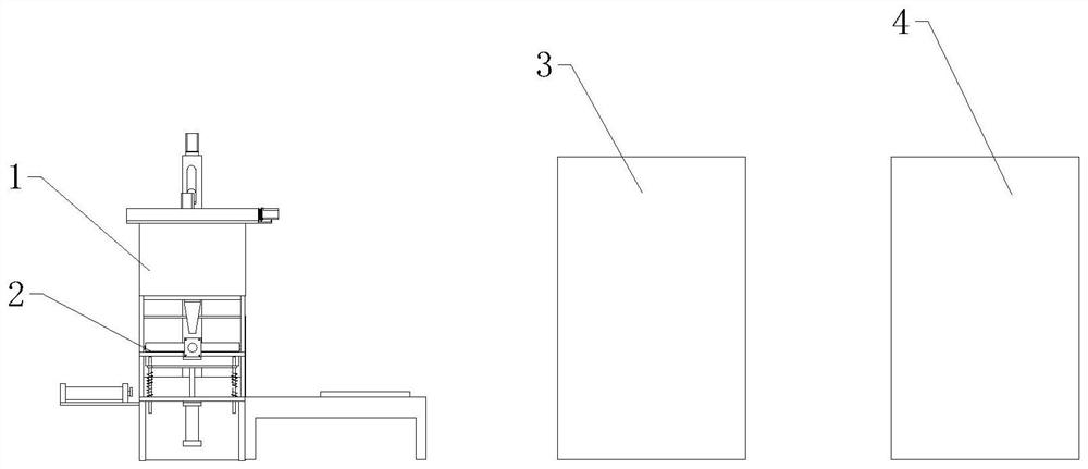
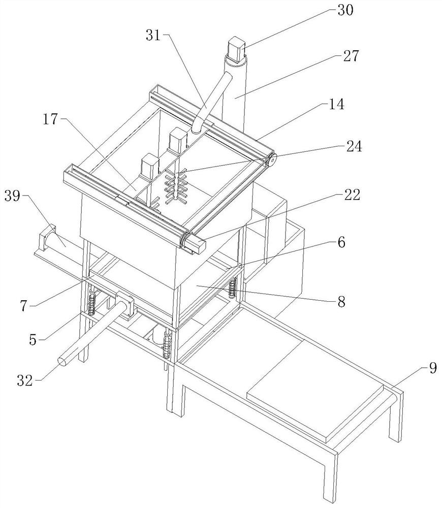
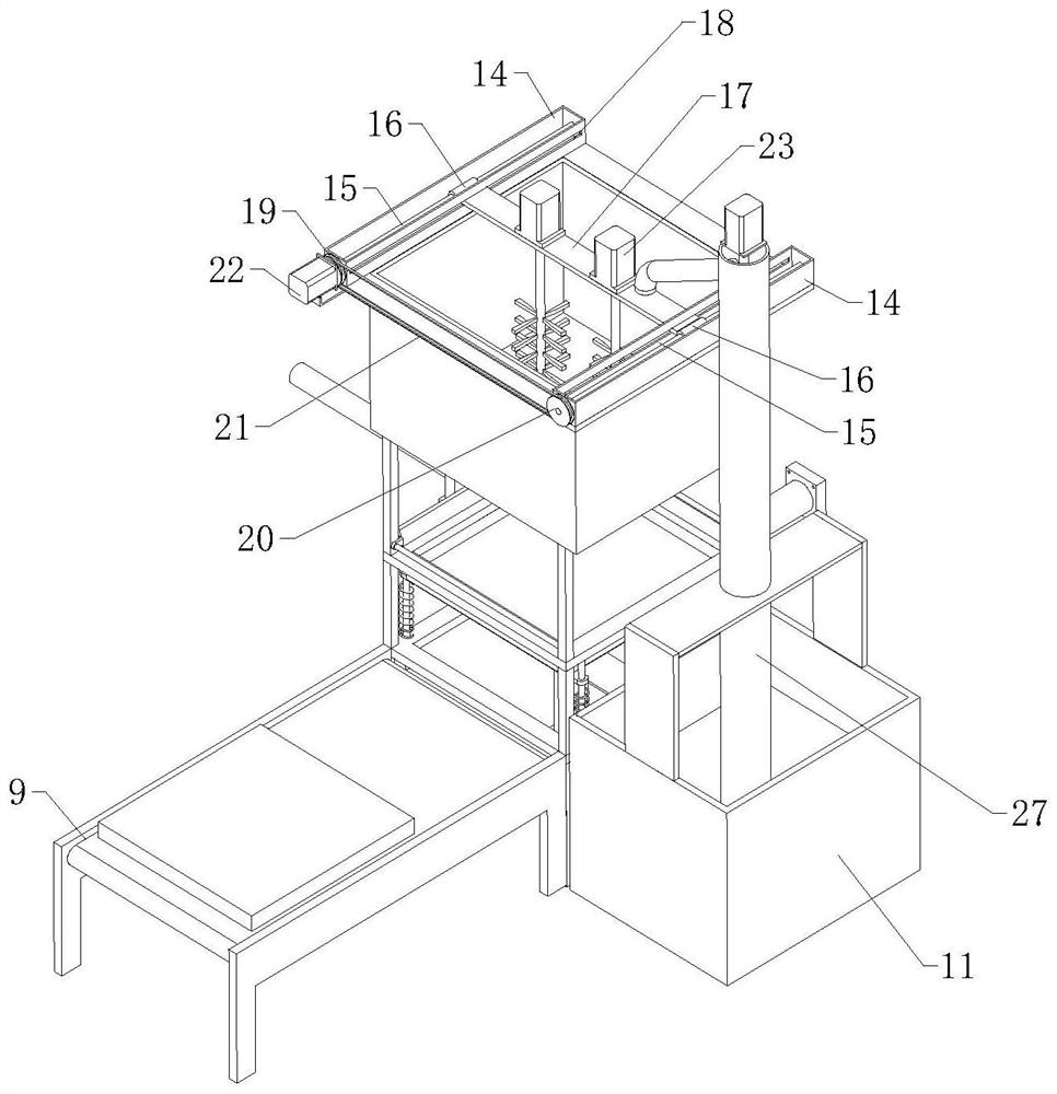
[0033] refer to Figure 1 to Figure 7As shown, a manufacturing equipment for a composite thermal insulation board, including a mixing mechanism 1, a superposition and smoothing mechanism 2, a drying mechanism 3 and an attachment mechanism 4, a superposition and smoothing mechanism 2, a rectangular frame 5, a material storage and smoothing assembly and a blanking Assemblies, the material-holding and smoothing assembly is arranged on the inner upper end of the rectangular frame 5, and the material-holding and smoothing assembly includes a rectangular material-holding box 6 for containing materials. The upper and lower ends of the rectangular material-holding box 6 are open structures, and the material-holding ...


PUM


Abstract

The invention relates to the technical field of composite board processing, in particular to manufacturing equipment for a composite insulation board. The manufacturing equipment comprises a mixing mechanism, superposed floating mechanism, a drying mechanism and an attaching mechanism. The superposed floating mechanism comprises a rectangular frame, a material accommodating floating assembly and an unloading assembly. The material accommodating floating assembly comprises a rectangular material accommodating box for accommodating a material, and a scraper blade capable of moving along a lengthdirection of the material accommodating box is arranged on one side above the material accommodating box. The unloading assembly comprises a supporting plate, an unloading conveyor is arranged on oneside of the rectangular frame, a push plate is arranged on the other side of the rectangular frame, and a recovery box is arranged on the side, far away from the push plate, of the rectangular frame.The mixing mechanism comprises a preparation box and a stirring assembly. An unloading pipe is arranged at the bottom of the preparation box. The drying mechanism and the attaching mechanism are separately arranged on one side of the unloading conveyor. According to the technical scheme, the strength of the insulation board is enhanced by splicing a mortar layer and glass fiber gridding cloth, the construction and transportation demands are met, and the thickness of an insulation layer is guaranteed and the engineering cost is not increased.

Description

technical field [0001] The invention relates to the technical field of composite board processing, in particular to a manufacturing equipment of a composite thermal insulation board. Background technique [0002] In new building construction and norms, energy-saving technology is being applied more and more, and the application of thermal insulation materials is the main development direction of energy-saving buildings. Especially, after using thermal insulation materials on the walls, the effect of warming in winter and cooling in summer is formed, and the energy saving is remarkable. As the danger of fire in high-rise buildings becomes increasingly prominent, in addition to the requirements for energy-saving and thermal insulation of building materials, its flame retardancy is also emphasized. Therefore, vitrified microspheres with non-combustible effects gradually enter the field of thermal insulation building materials. Chemical beads are processed into inorganic thermal...

Claims


Application Information

Patent Timeline
IPC IPC(8): B28B15/00B28C5/16B28C5/08B28B19/00E04B1/80
CPCB28B15/00B28B19/0092B28C5/0806B28C5/16E04B1/80
Inventor 李家行
Owner 李家行
Why Eureka
Try Eureka