
Anemometer tower microcosmic site selection method based on wind acceleration factor

An acceleration factor, micro-site selection technology, applied in the fields of instruments, marketing, data processing applications, etc., can solve the problems of labor, personnel, poor standardization and accuracy, time, and opportunity cost loss that take a long time to improve wind power. The effect of project wind measurement and micro-sitting level, improving accuracy, reducing development time and investment cost

Inactive Publication Date: 2020-11-20
HUANENG CLEAN ENERGY RES INST +1
View PDF5 Cites 8 Cited by
  • Summary
  • Abstract
  • Description
  • Claims
  • Application Information

AI Technical Summary

Problems solved by technology

The results of this site selection method are greatly affected by personal technical level factors, and the standardization and accuracy are poor; at the same time, due to the complex terrain and landform, the on-site survey work takes a long time and a lot of manpower and personnel, and the final wind measurement results It may not necessarily meet the needs of project evaluation, resulting in loss of time, opportunity cost, etc. and investment decision-making risks. Under the situation of increasingly scarce project resources, it will bring irreversible consequences to the development of the project

Method used


Image

  • Anemometer tower microcosmic site selection method based on wind acceleration factor
  • Anemometer tower microcosmic site selection method based on wind acceleration factor
  • Anemometer tower microcosmic site selection method based on wind acceleration factor

Examples


Embodiment Construction

[0024] The present invention will be further described in detail with the accompanying drawings and specific embodiments below, which are explanations rather than limitations of the present invention.

[0025] The microcosmic site selection method for anemometer tower based on wind acceleration factor of the present invention comprises the following steps:

[0026] Step 1: Obtain the digital topographic map of the wind farm area to be developed by downloading from the public data platform or drawing manually with the wind energy resource assessment software platform;

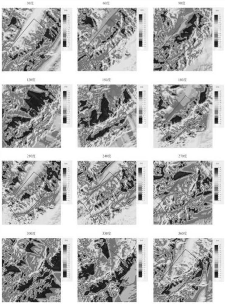
[0027] Step 2: After meshing the digital topographic map obtained in step 1, perform analysis and calculation based on computational fluid dynamics, and divide the wind farm area to be developed into 12 wind direction sectors or 16 wind direction sectors; through mesoscale reanalysis Or local meteorological stations to obtain the distribution data of wind acceleration factors in sectors of different wind directi...


PUM


Abstract

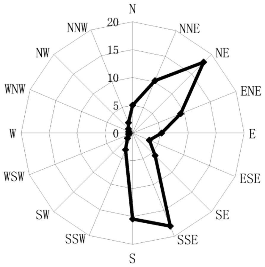
The invention discloses an anemometer tower microcosmic site selection method based on a wind acceleration factor, and belongs to the technical field of wind energy resource evaluation. The method comprises the following steps: firstly, obtaining a digital topographic map of a to-be-developed wind power plant area, carrying out mesh generation on the digital topographic map, and then carrying outdirectional calculation based on computational fluid dynamics to obtain wind acceleration factor distribution data in different wind direction sectors; then determining a plurality of alternative anemometer tower setting point locations by combining the main wind direction information and the wind acceleration factor distribution data; and finally, screening and rechecking the alternative anemometer tower setting point positions, and finally determining the anemometer tower setting point positions meeting the anemometer tower conditions. A reliable basis at the same stage and data collection degree is provided for microcosmic site selection of the anemometer tower. Therefore, the accuracy of site selection is remarkably improved, the situations that resource measuring points are not ideal,wind power plant development decisions are misled and the like possibly caused by the fact that a high-point anemometer tower is blindly selected according to experience are effectively avoided, andthe development time and investment cost of the wind power plant in complex terrains are greatly reduced.

Description

technical field [0001] The invention belongs to the technical field of wind energy resource assessment, and in particular relates to a microcosmic site selection method for anemometer towers based on wind acceleration factors. Background technique [0002] Usually under the same wind resource conditions, the main factor affecting the site selection of anemometer towers is the topography, which is generally divided into flat terrain and complex terrain. The southern region mainly has complex terrain, and the main factor affecting airflow in complex terrain is landform, followed by obstacles and surface roughness. In the past, the main method of wind measurement site selection for newly developed wind farm projects was to determine the location of wind measurement sites based on personal work experience, topographic maps and site survey results. The results of this site selection method are greatly affected by personal technical level factors, and the standardization and accu...

Claims


Application Information

Patent Timeline
Patent Type & Authority Applications(China)
IPC IPC(8): G06F30/28G06Q10/06G06Q30/02G06Q50/06G06F111/10G06F113/08G06F119/14
CPCG06Q10/0639G06Q30/0205G06Q50/06G06F30/28G06F2111/10G06F2113/08G06F2119/14Y02P90/82
Inventor 郭辰覃柏超刘鑫张国李家川张立英蔡安民邵振州邓明基
Owner HUANENG CLEAN ENERGY RES INST
Learn More