Lightning arrester

A lightning arrester and lightning arrester technology, applied in the field of lightning arresters, can solve the problems of simple structure and single function of the lightning arrester, and achieve the effects of good lightning protection effect, enhanced voltage division effect, and reduced lightning connection probability.

Pending Publication Date: 2020-11-20
扬州华铁机电集团有限公司 +1
View PDF0 Cites 0 Cited by
  • Summary
  • Abstract
  • Description
  • Claims
  • Application Information

AI Technical Summary

Problems solved by technology

[0005] The existing lightning arrester is simple in structure and single in function, and is passive lightning protection; therefore, it is necessary to design a lightning arrester that can be active lightning protection and increase lightning protection effect and safety

Method used


Image

  • Lightning arrester
  • Lightning arrester
  • Lightning arrester

Examples


Embodiment 1

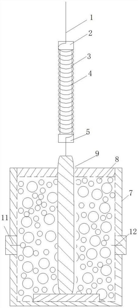
[0025] A lightning arrester is composed of a lightning rod 1, a lightning arrester and an iron core 3.

[0026] The top of the iron core 3 is provided with a first insulating block 2, and the bottom is provided with a second insulating block 5; On the top of the lightning protector; the iron core 3 is wound with a coil 4, the upper end of the coil 4 is connected to the lightning pin 1, and the lower end is connected to the inner core 9 of the lightning protector.

[0027] The lightning protector includes a conductive shell 7 with a hollow closed cavity inside, and a conductive inner core 9 is set in the cavity, the top of which is connected to the lower end of the coil through the cavity, and the bottom is placed at the bottom of the cavity through an insulating plate. The circumference of the inner core is filled with non-linear resistance particles 8, including ZnO non-linear resistance particles 8; the ground lead 10 is connected to the shell.

[0028] ZnO non-linear resis...

Embodiment 2

[0032] Based on the structure of Embodiment 1, a strut 6 is arranged between the lightning protector and the iron core 3 .

[0033] The pole 6 is an insulating hollow pole, and the iron core 3 is arranged on the top of the inner core 9 of the lightning arrester through the pole 6 , and the iron core 3 and the pole 6 are separated by the second insulating block 5 at the bottom of the iron core 3 . The lower end of the coil 4 is connected to the inner core 9 of the lightning arrester from the inner cavity of the rod.

Embodiment 3

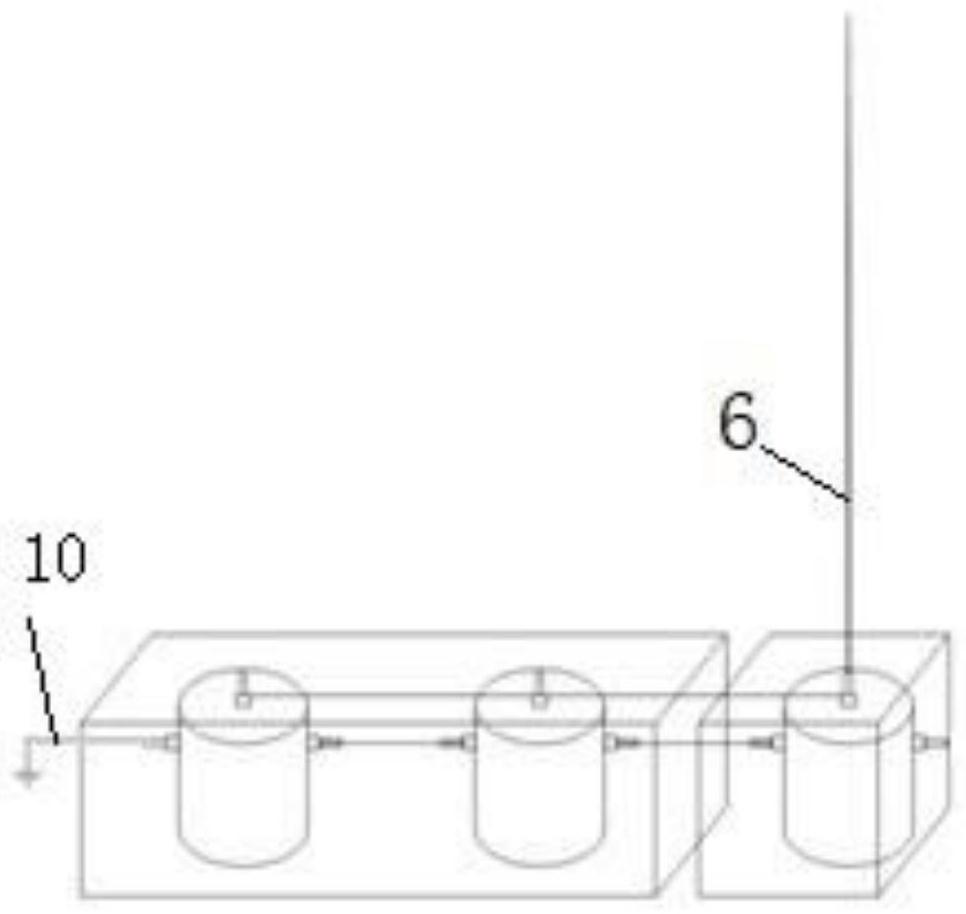
[0035] Based on the structure of Embodiment 2, the two sides of the lightning arrester are respectively provided with an incoming lead wire 11 and an outgoing lead wire 12 penetrating through the cavity;

[0036] Such as figure 2 Shown is a schematic diagram of a linear series connection structure, the lightning receptor 1 or through the support rod 6 is set on the top of the inner core 9 of the lightning arrester at one end, and the grounding lead 10 is connected to the shell 7 of the lightning arrester at the other end.

[0037] Such as figure 2 As shown, the shell 7 of the lightning arrester at the end of the serial connection is connected to the ground lead 10 .

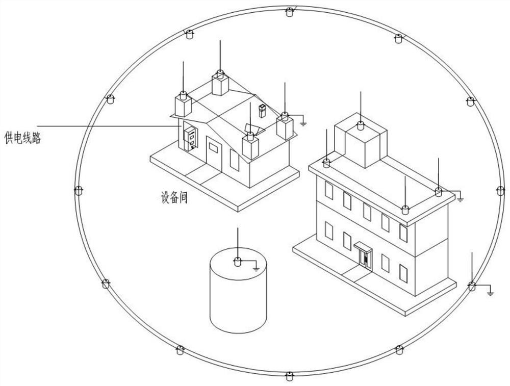
[0038] Such as image 3 Shown is a schematic structural diagram of area protection (including linear series connection and closed-loop series connection). The top of any lightning arrester is provided with a lightning terminal 1, and the grounding lead 10 is connected to the shell 7 of any lightning arrester....


PUM


Abstract

The lightning arrester comprises a lightning receiving needle, a lightning arrester body and an iron core, wherein insulating blocks are arranged at two ends of the iron core; the lightning receivingneedle is arranged at the top of the iron core, the iron core and the lightning receiving needle are separated by the insulating block at the top of the iron core, and the lightning arrester body is arranged at the bottom of the iron core; the exterior of the iron core is wounded with a coil; the upper end of the coil is connected with the lightning receiving needle, and the lower end of the coilis connected with the inner core of the lightning arrester body; the shell of the lightning arrester body is provided with the grounding lead, the electromagnet is additionally arranged at the top ofthe lightning arrester body, the lightning arrester body adsorbs charges in thunderstorm weather to conduct and magnetize the electromagnet, adsorption to surrounding charges is enhanced through the polarity of the magnetized electromagnet, then the effect of reducing discharge is achieved, and the lightning receiving probability is reduced. Nonlinear resistance particles in the lightning arresterneutralize and adsorb charges around the lightning receiving needle, so that the effect of voltage division for lightning receiving is achieved, and the voltage division effect is enhanced; the lightning arresters which are connected in series in a linear or closed-loop manner can be arranged in a regional range, so that the influence of electromagnetism on surrounding equipment is reduced in a targeted manner, and the lightning arrester has very high practicability and wide applicability.

Description

technical field [0001] The invention relates to a lightning arrester, which belongs to the technical field of lightning protection and lightning protection. Background technique [0002] The working principle of the lightning arrester: in thunderstorm weather, when a charged cloud layer appears over tall buildings and other structures, a large amount of charge is induced on the top of the lightning arrester and tall buildings and other structures. Since the needle of the lightning arrester is pointed, the tip of the conductor always accumulates the most charges during electrostatic induction. Like this, arrester has just gathered most of electric charge. [0003] Lightning arrester has formed a capacitor with these charged cloud layers again, because it is point, the two-plate that is this capacitor is very little over against area, electric capacity is also just very little, that is to say that electric charge that it can hold is seldom. And it has assembled most of elect...

Claims


Application Information

Patent Timeline
Patent Type & Authority Applications(China)
IPC IPC(8): H01T19/04H01F7/06H01C7/12
CPCH01C7/12H01F7/06H01T19/04
Inventor 徐志富徐帅臧权同
Owner 扬州华铁机电集团有限公司
Why Eureka
Try Eureka