Repair method of aeroengine blade

An aero-engine and repair method technology, applied in the direction of improvement of process efficiency, additive processing, energy efficiency, etc., can solve the problems of unable to form solidified structure with directional growth, unfavorable repair of high-temperature mechanical properties of blades, etc., and achieve good mechanical properties , reducing the effect of transverse grain boundaries

Active Publication Date: 2021-09-21
BEIHANG UNIV
View PDF5 Cites 0 Cited by
  • Summary
  • Abstract
  • Description
  • Claims
  • Application Information

AI Technical Summary

Problems solved by technology

[0003] The traditional additive manufacturing method currently used uses the method of rotating 67° between adjacent deposition layers for scanning, but the rotation of the scanning path is not conducive to the epitaxial growth of dendrites along the direction of heat flow, and cannot form a solidified structure with directional growth, which is not conducive to improving the repair process. High Temperature Mechanical Properties of Blades

Method used


Image

  • Repair method of aeroengine blade
  • Repair method of aeroengine blade
  • Repair method of aeroengine blade

Examples


Embodiment 1

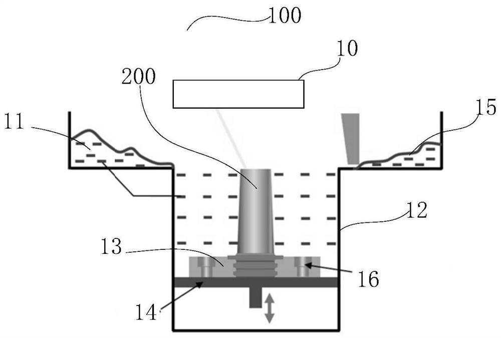
[0035] Such as figure 1 As shown, the laser molding module includes an optical window 10, a powder spreading device 11, a molding cavity 12, a substrate 13, a lifting mechanism 14, and a powder scraping device 15; the optical window 10 is located above the molding cavity 12, and a lifting mechanism is installed in the molding cavity 12 14. The substrate 13 is horizontally installed on the lifting mechanism 14, the powder spreading device 11 is located on one side of the molding cavity 12, and the powder scraping device 15 is located on the other side of the molding cavity 12.

[0036] It is worth mentioning that the lifting mechanism 14 can be a piston, and a groove for fixing the workpiece to be processed is opened in the middle of the base plate 13 , and a mounting hole is opened on the base plate 13 , and then fixed on the lifting mechanism 14 by bolts 16 .

[0037] The laser light emitted by the laser reaches the scanning system after passing through the light guide system...


PUM

PropertyMeasurementUnit
yield strengthaaaaaaaaaa
tensile strengthaaaaaaaaaa

Abstract

The invention relates to the field of repairing key aviation components, in particular to a method for repairing an aeroengine blade, comprising the following steps: fixing the blade to be repaired in a forming cavity of a selective laser melting device; laying powder in the forming cavity to cover the blade In the area to be repaired, use the laser beam to scan and melt the powder along the set path with the set power, and the scanning path is along the chord direction of the blade; after the molten pool solidifies, a deposition layer is formed, and the laser beam power is reduced without adding powder Scan the deposition layer again according to the set path to eliminate the crystal grains on the surface of the deposition layer, and then form a remelted layer; repeat the above operations until the repair is completed, so that the powder is deposited on the blade layer by layer along the chord direction of the blade , the columnar grains can grow epitaxially and directionally along the direction of heat flow, reducing the transverse grain boundaries along the chord direction of the blade, so that the repaired blade exhibits good mechanical properties at high temperatures.

Description

technical field [0001] The invention relates to the field of repairing key aviation parts, in particular to a repairing method for an aeroengine blade. Background technique [0002] Titanium alloys and nickel-based superalloys have very superior comprehensive mechanical properties, and are the main materials for aeroengine blades, blisks and overall blisks. Due to the harsh service environment of aero-engines, the blades will be cracked, corroded, and worn under long-term high-temperature and high-pressure conditions, resulting in failure and scrapping of the workpiece. Traditional repair methods such as argon tungsten arc welding and linear friction welding are prone to defects such as pores, hydrogen embrittlement, and cracks. In view of the above problems, there is an urgent need to adopt an advanced repair technology to achieve high-quality and efficient repair of damaged parts, restore the geometric and mechanical properties of damaged parts, prolong their service life...

Claims


Application Information

Patent Timeline
Patent Type & Authority Patents(China)
IPC IPC(8): B22F7/06B22F3/105B22F3/24B33Y10/00B33Y40/20
CPCB22F3/24B22F7/062B22F2003/248B22F2007/068B33Y10/00B33Y40/20Y02P10/25
Inventor 何蓓张述泉田象军李卓朱言言程序
Owner BEIHANG UNIV
Why Eureka
Try Eureka