Multi-dimensional expansion robot

A robot, multi-dimensional technology, applied in the directions of manipulators, conveyor objects, transportation and packaging, etc., can solve the problems of small space operation range, high space occupancy rate, small carrying capacity, etc., to widen the working range and low space occupancy rate. , reliable operation effect

Pending Publication Date: 2020-11-24
ZAOZHUANG UNIV
0 Cites 3 Cited by

AI-Extracted Technical Summary

Problems solved by technology

Truss-type mechanisms include cranes, quay cranes, cantilever cranes, etc., all of which adopt linear motion mechanisms, which generally have problems such as high space occupation rate, small space operating range, poor flexibility, and low efficiency...

Method used

The form of terminal effector is varied, can be mechanical arm (as shown in Figure 1), hoisting gourd, industrial gripper etc., its selection principle is randomly selected according to the load-carrying capacity and functional requirements of multi-dimensional expansion robot, linear movement mechanism The mobile end provides a variety of interface methods to facilitate the connection and installation of the end effector.
Traveling mechanism comprises traveling frame and supporting traveling wheel, and supporting traveling wheel is installed on traveling frame, and each traveling frame is equipped with two supporting traveling wheels, in order to improv...

Abstract

The invention relates to a multi-dimensional expansion robot, and belongs to an industrial robot. According to the technical scheme, the multi-dimensional expansion robot comprises a circular track, acircular driving device, a linear extending mechanism, a linear moving mechanism and a tail end executing mechanism; the circular track is provided with a hoisting mounting frame, the hoisting mounting frame is fixed to at least three positions of the circular track, and the hoisting mounting frame is fixed above a plant or a suspended mounting fixing position; and a walking mechanism and a geardriving mechanism are arranged between the circular driving device and the circular track, the walking mechanism circularly walks and moves along the track surface on the circular track, and the geardriving mechanism drives the circular driving device to rotate around the center of the circular track on the circular track. The robot is installed above the plant or the top of other hoisting supports, and the problems of arm expansion limitation and high basic space occupation rate of grabbing robots, assembling and producing robots and material carrying robots are solved.

Application Domain

Technology Topic

Image

  • Multi-dimensional expansion robot
  • Multi-dimensional expansion robot
  • Multi-dimensional expansion robot

Examples

  • Experimental program(1)

Example Embodiment

[0025] The specific structure of the present invention will be further described below:
[0026] The structural installation relationship and function of each component of the patent of the invention are explained:
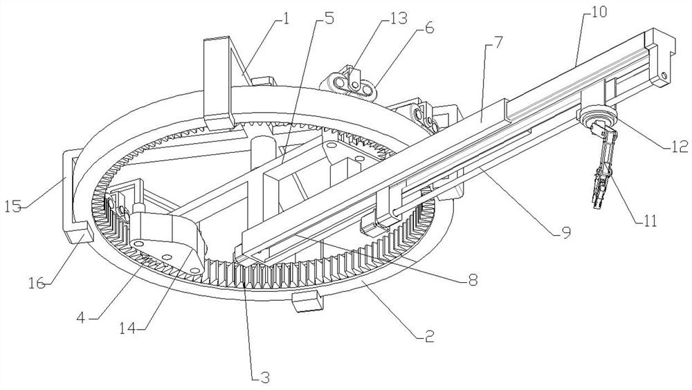
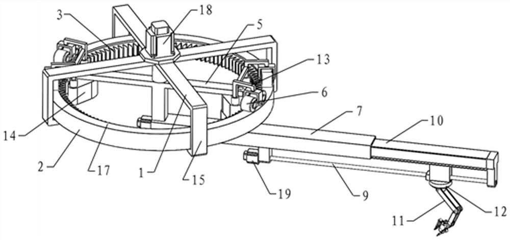
[0027] The device includes a hoisting installation frame, a circular track, a circular drive device, a linear extension mechanism, a linear movement mechanism and an end effector.
[0028] Hoisting mounting frame: The hoisting mounting frame is used for the installation and fixation of multi-dimensional expansion robots, and is fixed on the upper part of the factory interior or on the top of the open-air hoisting bracket by hoisting installation. In the present invention, the hoisting installation frame is a cross, and the four ends of the cross extend downward from the hanging plate, and the bottom of the hanging plate extends inwardly with the supporting plate to support and fix the bottom of the circular track.
[0029] The circular track is an annular track, the circular track is located under the hoisting installation frame, and the supporting plate extended from the hoisting installation frame supports and fixes the lower side of the circular track. The circular track is the track and support mechanism for the circular drive device to run.
[0030] The circular drive device includes a rotating frame, a traveling mechanism and a gear drive mechanism. The turret is arranged under the hoisting installation frame, and the hoisting installation frame is equipped with a rotating motor. The output shaft of the rotating motor is connected to the rotation center of the turret. The rotation of the rotating motor controls the running speed of the circular driving device and the turret is on the circular track The rotational position.
[0031] The gear drive mechanism includes a circular rack on the side of the circular rail and two sets of driving gears meshing with the circular rack. The driving gear is mounted on a gear mounting frame, which is fixed to the end of the rotating frame and rotates. The rotation of the motor output shaft drives the rotation of the turret, and the rotation of the turret drives the meshing movement of the driving gear and the circular rack.
[0032] The walking mechanism includes a walking frame and a supporting walking wheel, the supporting walking wheel is installed on the walking frame, and each walking frame is equipped with two supporting walking wheels to improve the carrying capacity and walking stability of the supporting walking wheel. The walking frame is fixed on the gear mounting frame at the end of the rotating frame. The track surface of the circular track is the upper ring surface, and the rotation and rotation drive the supporting traveling wheel to walk along the ring surface and run in a circular loop. When the turret has a linear structure, its two ends are respectively provided with walking mechanisms, and the two sets of walking mechanisms are symmetrically arranged with respect to the rotation center of the turret, so as to realize the weight balance of the walking mechanism supporting the turret and the fixedly connected mechanisms.
[0033] The walking mechanism first is to support the weight of the turret and the lower bearing linear extension mechanism, linear moving mechanism, end effector 11 and end effector clamping objects; the second is the circular walking function to complete the circumference of the end effector clamping object Space movement.
[0034] The linear extension mechanism is fixed at least two points on the lower part of the rotating frame to achieve rigid fixation. The outermost end of the linear extension mechanism extends over the edge of the circular track.
[0035] The linear extension mechanism has a rectangular cross-section, a sliding groove is opened inside to set a first-level telescopic arm, and the first-level linear moving mechanism is between the telescopic arm and the linear extension mechanism. The primary linear moving mechanism is a screw nut transmission pair, one or both ends of the screw are fixed in the sliding groove of the linear extension mechanism through a bearing, and a drive motor is arranged at the inner end of the linear extension mechanism.
[0036] A transmission nut is fixed on the first-level telescopic arm, and the transmission nut is matched with the lead screw. The rotation of the rotating motor drives the lead screw to rotate, and then drives the transmission nut and the first-level telescopic arm to move to realize the telescopic movement of the first-level telescopic arm.
[0037] The secondary linear movement mechanism is also a screw nut transmission mechanism, which is arranged under the telescopic arm, and the end effector is arranged on the transmission nut of the secondary linear movement mechanism. The drive motor of the secondary linear movement mechanism drives the screw to rotate, and the transmission nut As the lead screw rotates, it moves along the axial direction of the lead screw, driving the end effector to move forward and backward along the primary telescopic arm.
[0038] The primary linear moving mechanism can be one of a rack and pinion transmission pair, a screw nut transmission pair, a timing belt transmission pair, and a hydraulic cylinder type pushing mechanism. The secondary linear moving mechanism can be a variety of transmission modes such as lead screw nut, timing belt, rodless cylinder, etc.
[0039] The linear moving mechanism and the telescopic arm can realize the multi-dimensional expansion of the two-stage telescopic operation of the robot operating space, and increase the operating range of the operation.
[0040] The end effector is fixed on the base of the end effector and can be used as the basic connecting seat of various types of robots. The first solution is to solve the problem of intensive installation of the base space of the robot. The end effector base is installed on the transmission nut of the linear movement mechanism.
[0041] The end effector has various forms, which can be a mechanical arm (such as figure 1 ), hoisting hoist, industrial gripper, etc. The selection principle is randomly selected according to the multi-dimensional expansion of the robot's carrying capacity and functional requirements. The mobile end of the linear moving mechanism provides a variety of interface methods to facilitate the connection and installation of the end effector.
[0042] The working process implementation description of the present invention, taking transportation as an example, when the industrial site needs to transport a known object to a designated position, the rotating motor drives the turret to rotate, and the linear extension mechanism on the turret rotates to the position above the material to be transported , At least below the realization direction of the linear extension structure. At this time, if the position of the material exceeds the range of the linear extension mechanism, the secondary linear movement mechanism drives the end effector to move to the top of the material. If the secondary linear movement mechanism drives the end effector to be insufficient to reach the material position, the primary linear movement mechanism drives The first-level telescopic arm is extended to realize the end effector reaching above the material.
[0043] The end effector grabs the material and lifts it, and then rotates the motor, the secondary linear moving mechanism or the primary linear moving mechanism works synchronously or asynchronously to move the material to the required position and complete the entire handling process.

PUM

no PUM

Description & Claims & Application Information

We can also present the details of the Description, Claims and Application information to help users get a comprehensive understanding of the technical details of the patent, such as background art, summary of invention, brief description of drawings, description of embodiments, and other original content. On the other hand, users can also determine the specific scope of protection of the technology through the list of claims; as well as understand the changes in the life cycle of the technology with the presentation of the patent timeline. Login to view more.

Similar technology patents

Automatic pattern cutting equipment

Owner:南京深农智能装备有限公司

Classification and recommendation of technical efficacy words

  • Reduce space occupancy
  • Large operating space

Multifunctional rotary embedded combined bookcase

InactiveCN108835939AReduce space occupancyAvoid accidental collision with foreign objectsBook cabinetsConvertible furnitureDrive motorEngineering
Owner:邓文

Large-size multi-axis-linkage electrolytic machine tool

ActiveCN103464845ALarge operating spaceEasy to install and adjustMachining working media supply/regenerationElectric circuitsMachine toolPulse power supply
Owner:NANJING UNIV OF AERONAUTICS & ASTRONAUTICS
Why Eureka
Try Eureka