
Locomotive bogie driving device

A locomotive bogie and driving device technology, which is applied to transmission devices, locomotives, motor vehicles and other directions driven by electric motors, can solve the problems of limited maximum transmission ratio of single-stage transmission, cannot be increased or increased without limit, etc. The driving torque and driving power are reduced, the limit speed is increased, and the wear matching is good.

Pending Publication Date: 2020-11-24
ZHUZHOU ELECTRIC LOCOMOTIVE CO
View PDF6 Cites 2 Cited by
  • Summary
  • Abstract
  • Description
  • Claims
  • Application Information

AI Technical Summary

Problems solved by technology

Due to the limit of the bottom of the gearbox (the maximum number of teeth of the driven gear is limited when the gear module is given) and the minimum number of teeth of the driving gear (generally not less than 17), the maximum transmission ratio of the single-stage transmission is limited, so it can only be increased The torque of the traction motor, and the increase of the torque of the traction motor needs to be realized by increasing the outer diameter of the traction motor, and the outer diameter of the traction motor is limited by the gear center distance between the driving gear and the driven gear and cannot be increased all the time (the gear center distance is the driving The sum of the teeth of the gear and the driven gear is multiplied by the modulus and divided by 2)
Therefore, the torque of the traction motor of the traditional driving device has a ceiling, which cannot be increased without limit

Method used


Image

  • Locomotive bogie driving device
  • Locomotive bogie driving device
  • Locomotive bogie driving device

Examples


Embodiment Construction

[0023] The present invention will be further described below in conjunction with specific preferred embodiments, but the protection scope of the present invention is not limited thereby.

[0024] For the convenience of description, the relative positional relationship of each component, such as: the description of up, down, left, right, etc., is described according to the layout direction of the drawings in the specification, and does not limit the structure of this patent.

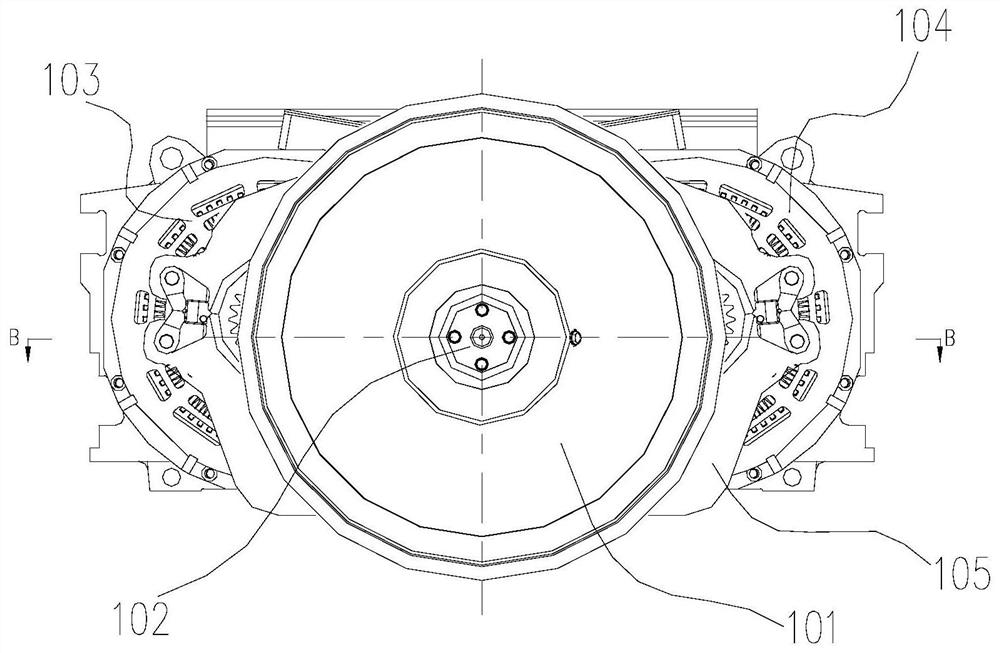
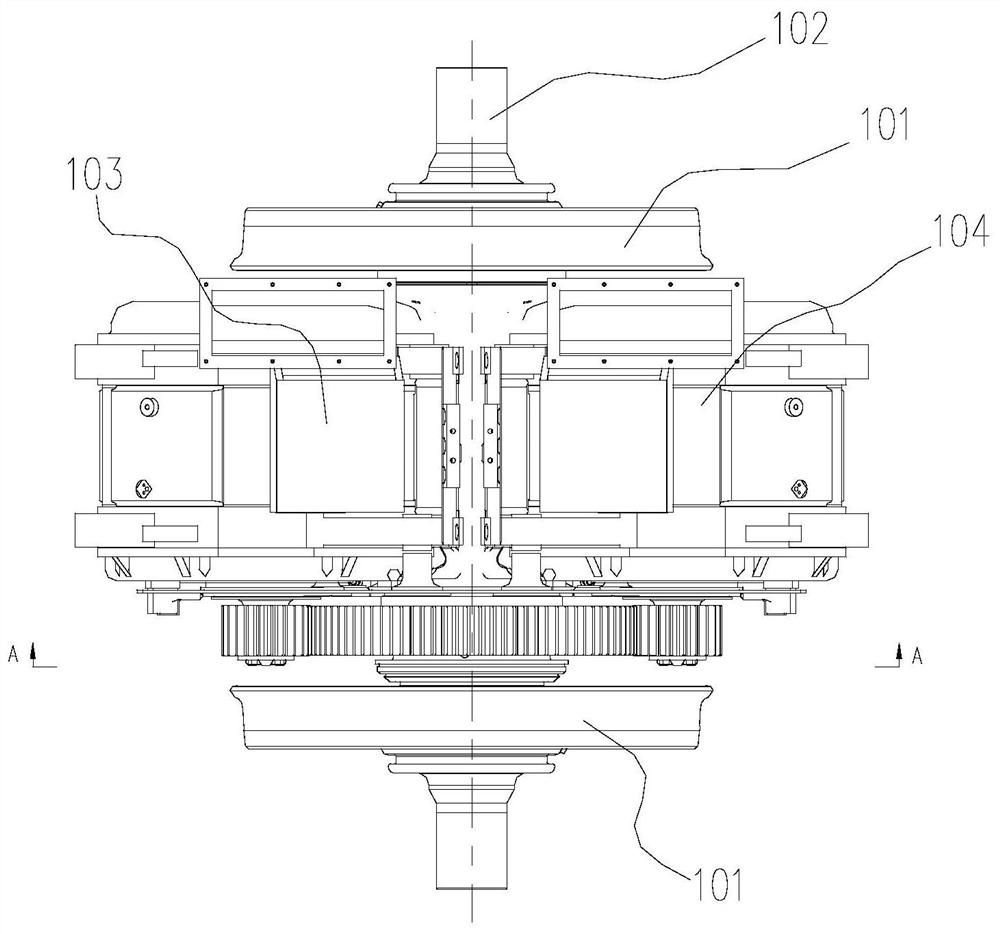
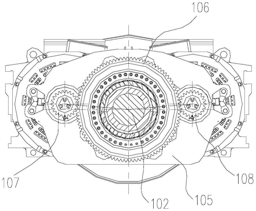
[0025] Such as Figure 1 ~ Figure 4 As shown, an embodiment of the locomotive bogie driving device of the present invention includes a wheel pair (including wheels 101 and axle shaft 102), traction motor 103, traction motor 104, driven bull gear 106, driving pinion 107, driving pinion 108 and Gearbox 105. The traction motor 103 has a rotating shaft 111 and a transmission end bearing 113 , and the driving pinion 107 is cantilever mounted on the transmission end of the rotating shaft 111 . The traction mo...


PUM


Abstract

The invention discloses a locomotive bogie driving device. The locomotive bogie driving device comprises one axle, wherein a driven gearwheel is arranged on the axle in an interference mode, and identical traction motors are symmetrically arranged on the two sides of the axle; and driving pinions are arranged on rotating shafts of the traction motors in an interference mode correspondingly, and the driving pinions of the traction motors on the two sides of the axle are simultaneously meshed with the driven gearwheel to form a transmission gear pair. The driving torque and the driving power ofthe locomotive bogie driving device can be obviously increased and even doubled; and for appointed single-shaft traction power and traction force, the size and the weight of the single traction motorof the locomotive bogie driving device are smaller, so that huge space convenience is provided for a bogie traction rod to pass through the position below the traction motors; and in addition, the abrasion matching performance of the driving pinions and the driven gearwheel of the locomotive bogie driving device is better.

Description

technical field [0001] The invention relates to a railway locomotive bogie, in particular to a driving device for a locomotive bogie. Background technique [0002] At present, the driving devices of locomotive bogies are all driven by a single motor and a single wheel set, and except for the driving devices using permanent magnet direct drive technology, the rest of the locomotive driving devices are all geared to match the traction characteristics of the traction system. [0003] The current single-motor-driven single-wheel drive device technology faces the following difficult challenges: [0004] For high-speed locomotives, it is necessary to pursue as large a starting traction force as possible. The starting traction force is obtained by the following formula: F=M×i / R [0005] Among them: F is the starting traction; M is the torque of the traction motor; i is the transmission ratio, that is, the number of teeth of the driven gear / the number of teeth of the driving gear;...

Claims


Application Information

Patent Timeline
Patent Type & Authority Applications(China)
IPC IPC(8): B61C3/00B61C9/50
CPCB61C3/00B61C9/50B61C9/48
Inventor 邓小星沈龙江李冠军申长宏谢加辉谭桐彭波廖志伟朱向阳曾艳梅刘金菊李燕慧蔡超秦烺
Owner ZHUZHOU ELECTRIC LOCOMOTIVE CO
Learn More