
Rotor untwisting toothed plate with low feeding resistance

A tooth plate and rotor technology, applied in the field of cellulose fiber preparation, pulping and papermaking, can solve the problems of easy broken teeth, high service life, high power consumption, and unsmooth feeding, so as to adjust the length of cellulose fibers, improve the The beating degree and yield, the effect of improving the degree of brooming

Pending Publication Date: 2020-11-24
南通华严磨片有限公司
View PDF8 Cites 1 Cited by
  • Summary
  • Abstract
  • Description
  • Claims
  • Application Information

AI Technical Summary

Problems solved by technology

[0006] The problem with the above-mentioned debonding tooth plate of the prior art is that the tooth plate structure of the decomposing tooth plate is still a discontinuous trapezoidal or triangular bump, which makes it difficult to work under low clearance conditions and to decompose and crush the cellulose fibers. , it is not easy to adjust the fiber length of cellulose, it has the disadvantages of low wear resistance, poor impact resistance, easy broken teeth, end of service life and high power consumption, it is difficult to improve the degree of beating and yield, and it is impossible to improve the fiber of cellulose Separation degree; the resistance of feeding is large, and the diversion effect of raw materials entering the deflagging tooth plate is weak, so that the feeding is not smooth, causing the raw materials to often block the tooth plate and stop the machine, which seriously affects the production and seriously restricts the use of the deflaking machine. Effect and scope of application

Method used


Image

  • Rotor untwisting toothed plate with low feeding resistance

Examples


Embodiment Construction

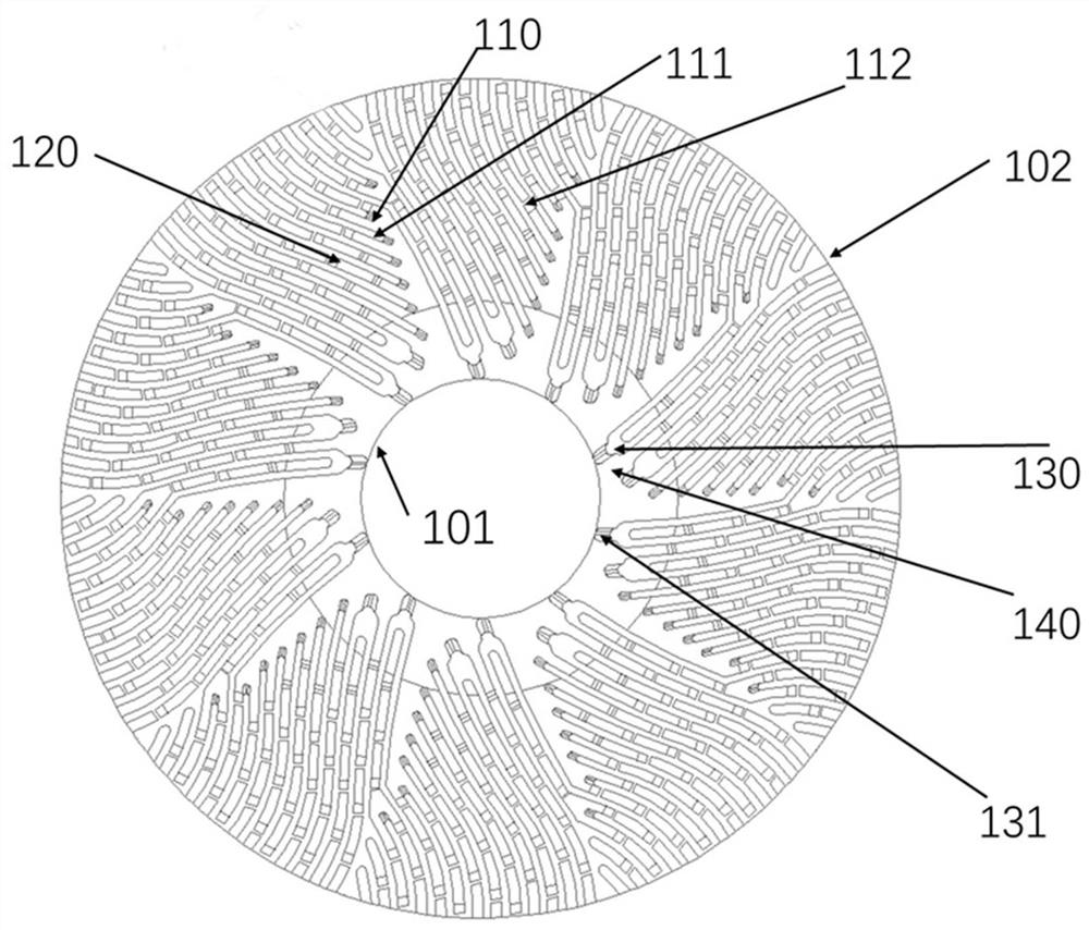
[0021] Such as figure 1 As shown, a rotor deflaking tooth plate with low feed resistance, the rotor deflaking tooth plate is installed on the rotating seat of the deflaking machine, and the rotor deflaking tooth plate is used to cooperate with the stator deflaking tooth plate of the static seat of the deflaking machine.

[0022] The rotor decompression tooth plate faces the stator decompression tooth plate and is set in a plane contact manner, non-engaging, so it can work under the condition of a lower clearance, and has the functions of improving the decomposition and crushing of cellulose fibers, adjusting the length of cellulose fibers, and wear resistance. It has the advantages of high strength, good impact resistance, not easy to break teeth, long service life and saving power consumption.

[0023] There are 10 rack units distributed in the circumferential direction of the rotor loosening tooth plate, and the rack unit is arranged between the inner edge 101 and the outer ...


PUM

PropertyMeasurementUnit
widthaaaaaaaaaa
heightaaaaaaaaaa
widthaaaaaaaaaa

Abstract

The invention discloses a rotor untwisting toothed plate with low feeding resistance. The rotor untwisting toothed plate is mounted on an untwisting machine rotating seat; the rotor untwisting toothedplate is used for being matched with a stator untwisting toothed plate of an untwisting machine static seat; the rotor untwisting toothed plate faces the stator untwisting toothed plate and is matched with the stator untwisting toothed plate in a plane contact manner; a plurality of rack units are distributed in the circumferential direction of the rotor untwisting toothed plate; the racks extendfrom the inner edge to the outer edge in the radial direction and are in an S shape in the longitudinal depth direction; a tooth groove is formed between every two adjacent racks in each rack unit; aplurality of blocking dams are transversely arranged in each tooth groove; every two adjacent racks are combined into an integrated wide tooth when each rack unit is located at the position 20-200 mmaway from the inner edge; and a bionic duckbilled flow guide end is arranged at the end, directly facing the inner edge, of each integrated wide tooth. The rotor untwisting toothed plate has the advantages of being high in abrasion resistance, good in impact resistance, not prone to tooth breakage, long in service life, capable of reducing power consumption and the like.

Description

technical field [0001] The invention relates to the fields of pulping and papermaking, and cellulose fiber preparation, in particular to a rotor fluffing tooth plate with low feeding resistance. Background technique [0002] The flaking machine is composed of a movable ring gear set and a fixed ring gear set opposite to each other; during the flaking operation, the cellulose raw material flows in from the center port of the fixed ring gear set, and flows along the gap between the movable ring gear and the fixed ring gear to the outer periphery. The direction flows while being undone. At present, the known debonding tooth plates are mainly labyrinth-shaped structures, and the tooth plate structures are all discontinuous trapezoidal or triangular protrusions. During operation, the contact surfaces of the rotor decompression tooth plates and the rotor decompression tooth plates are meshing, non-planar contact; When the movable ring gear rotates, it forms a meshing shape with t...

Claims


Application Information

Patent Timeline
Patent Type & Authority Applications(China)
IPC IPC(8): D21D1/30
CPCD21D1/306
Inventor 蒋小军罗冲田晓辉严震秦琦李慧帆赵杨蒋思蒙宋萍
Owner 南通华严磨片有限公司
Learn More