
System for large production increasing, nitrogen reduction and consumption reduction of KHD type cement kiln

A cement kiln, a large-scale technology, applied to the furnace, furnace components, preheating costs, etc., can solve the problems of not being able to guarantee the production capacity, the clogging of the cyclone, and the high cross-sectional wind speed, so as to reduce the resistance and heat exchange. Good, the effect of increasing the volume

Pending Publication Date: 2020-11-24
SHANDONG TAIAN HENGYE MACHINERY
View PDF0 Cites 2 Cited by
  • Summary
  • Abstract
  • Description
  • Claims
  • Application Information

AI Technical Summary

Problems solved by technology

Severe dust at the elbow where the direction changes quickly, causing environmental pollution, and the wall of the kiln head cyclone (sedimentation chamber) is crusted and collapsed, causing the clogging of the cyclone;
[0004] 2. The existing tube furnace is relatively small, and the cross-sectional wind speed is relatively large. Under the output of 5500t / d, the outlet of the calciner is about 880°C, and the decomposition rate of the materials entering the kiln is about 90%. The capacity of the existing calciner can meet the needs of pulverized coal The residence time requirement in the furnace, if the clinker output increases, the gas stays in the furnace will be shortened, the resistance will increase, and the production capacity cannot be guaranteed; therefore, it is necessary to improve the existing cement production line

Method used


Image

  • System for large production increasing, nitrogen reduction and consumption reduction of KHD type cement kiln
  • System for large production increasing, nitrogen reduction and consumption reduction of KHD type cement kiln
  • System for large production increasing, nitrogen reduction and consumption reduction of KHD type cement kiln

Examples


Embodiment Construction

[0025] The following will clearly and completely describe the technical solutions in the embodiments of the present invention with reference to the accompanying drawings in the embodiments of the present invention. Obviously, the described embodiments are only some, not all, embodiments of the present invention.

[0026] In describing the present invention, it should be understood that the terms "upper", "lower", "front", "rear", "left", "right", "top", "bottom", "inner", " The orientation or positional relationship indicated by "outside", etc. is based on the orientation or positional relationship shown in the drawings, and is only for the convenience of describing the present invention and simplifying the description, rather than indicating or implying that the referred device or element must have a specific orientation, so as to Specific orientation configurations and operations, therefore, are not to be construed as limitations on the invention.

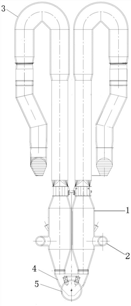
[0027] refer to figure 1...


PUM


Abstract

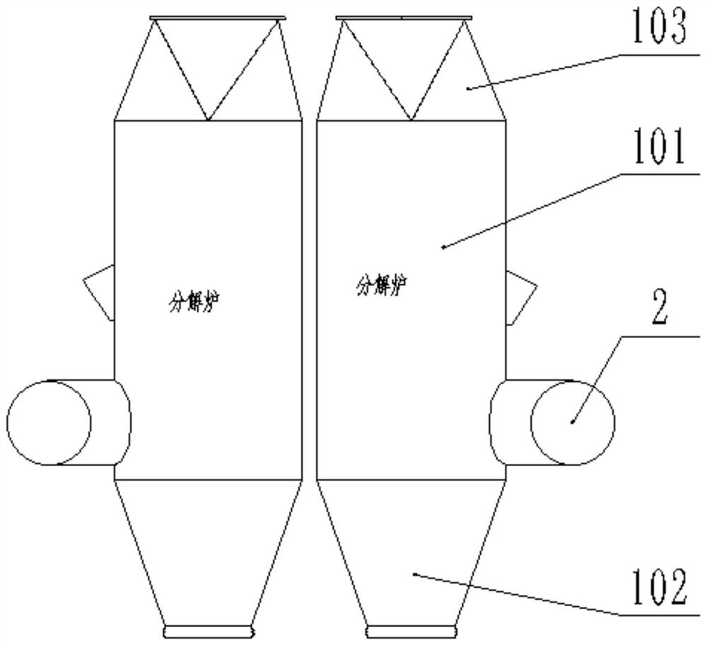
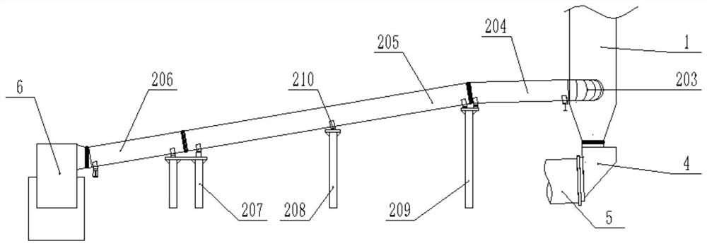
The invention discloses a system for large production increasing, nitrogen reduction and consumption reduction of a KHD type cement kiln, and relates to the technical field of cement production. A preheater system is reconstructed on the basis of an original dry method production line cement kiln, the large production increasing, lower power consumption, lower coal consumption and lower NOx emission of the system can be achieved. An original tube furnace is changed into a decomposing furnace with larger furnace capacity, a structural form and a furnace entering position of a tertiary air pipeare changed, and a new gooseneck pipe is added. According to the system disclosed by the invention, the furnace capacity of a decomposing furnace is larger, the retention time of raw materials in thepreheater is longer, the decomposition rate is increased, and production increasing is facilitated; a denitration reduction area is arranged in a new decomposing furnace cone, a production process ofcoal feeding in a tertiary air pipe is changed, and the situation that a large amount of NOx generated in the tertiary air pipe can only be reduced by using a denitration agent is avoided. By changingthe structural forms of the tertiary air pipe and the decomposing furnace, the resistance in the system is greatly reduced, the power consumption is correspondingly reduced, the furnace capacity is increased, the burn-off rate of pulverized coal is increased, and the coal consumption is reduced.

Description

technical field [0001] The invention relates to the technical field of cement production, in particular to a KHD type cement kiln system for greatly increasing production, reducing nitrogen and reducing consumption. Background technique [0002] The cement production line of the existing German Humboldt Widak company (KHD) has the following deficiencies: [0003] 1. The structure of the existing tertiary air duct is to take the air from the kiln hood and go down horizontally to the kiln tail, and then merge with the original tube furnace at the height of the tube furnace after the kiln tail is bent. Severe dust at the elbow where the direction changes quickly, causing environmental pollution, and the wall of the kiln head cyclone (sedimentation chamber) is crusted and collapsed, causing the clogging of the cyclone; [0004] 2. The existing tube furnace is relatively small, and the cross-sectional wind speed is relatively large. Under the output of 5500t / d, the outlet of the...

Claims


Application Information

Patent Timeline
IPC IPC(8): F27D17/00F27D13/00F27D7/06
CPCF27D7/06F27D13/00F27D17/002F27D17/004F27D2007/063F27D2017/005
Inventor 朱乾夏念丰范培昕
Owner SHANDONG TAIAN HENGYE MACHINERY
Learn More