Magnet temperature control device of nuclear magnetic resonance equipment

A technology of nuclear magnetic resonance and temperature control device, which is used in magnetic resonance measurement, measurement device, measurement of magnetic variables, etc., can solve the problems of wind speed and flow deviation, cumbersome and inconvenient operation, insufficient heating of magnets, and achieve good economy. , reduce sticky stock, clean, efficient and convenient effect

CN111983535AInactive Publication Date: 2020-11-24李宁菘
11 Cites 0 Cited by

Patent Information

Authority / Receiving Office
CN · China
Patent Type
Applications(China)
Current Assignee / Owner
Publication Date
2020-11-24
Estimated Expiration
Not applicable · inactive patent

Smart Images

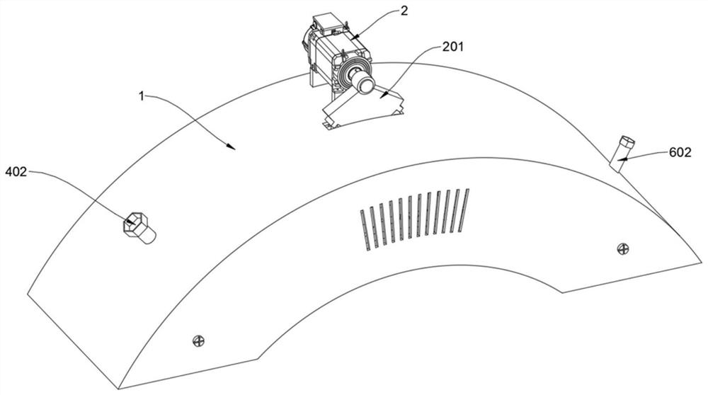
  • Figure 1
    Figure 1
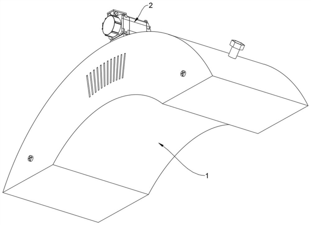
  • Figure 2
    Figure 2
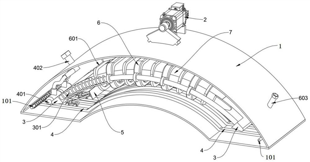
  • Figure 3
    Figure 3
Patent Text Reader

Abstract

The invention discloses a magnet temperature control device for nuclear magnetic resonance equipment, relates to the technical field of the nuclear magnetic resonance equipment, and solves the problems that an existing temperature control device adopts hot air blowing heating, the hot air is mostly directional incoming air, only single-side blowing heating can be performed on the magnet, and blowing dead angles exist. The magnet temperature control device of the nuclear magnetic resonance equipment comprises a motor, an arc-shaped clamping plate, adsorption strip plates and a stress push plate, the motor comprises a sector gear, the middle of the top end of an arc-shaped shell is provided with the motor in a supporting mode, and a rotating shaft of the motor is sleeved with a sector gear;the arc-shaped shell comprises a transverse support positioning shaft; and two transverse support positioning shafts are symmetrically supported and welded at the root positions of the left side and the right side of the inner space of the arc-shaped shell. The front and rear groups of adsorption strip plates can intermittently slide back and forth oppositely in a reciprocating manner to adsorb and clean deposited dust swept from the inner wall of the bottom of the arc-shaped shell, so that the trouble of manual cleaning is saved.
Need to check novelty before this filing date? Find Prior Art

Description

technical field

[0001] The invention relates to the technical field of nuclear magnetic resonance equipment, in particular to a magnet temperature control device for nuclear magnetic resonance equipment. Background technique

[0002] Nuclear Magnetic Resonance refers to a physical process in which the atomic nucleus with a non-zero magnetic moment is under the vertical action of the main magnetic field and the radio frequency field, and the spin energy level undergoes Zeeman splitting, and the nucleus absorbs radio frequency energy. It has other detection methods such as non-destructive testing and rich testing information. Incomparable many advantages. The magnetic field strength of the permanent magnet magnetic field will change as the ambient temperature changes, thus affecting the detection of nuclear magnetic resonance signals. The application range of nuclear magnetic resonance technology is very wide, covering many fields such as biology, medicine, chemistry, food, p...

Examples

Embodiment Construction

[0032] The following will clearly and completely describe the technical solutions in the embodiments of the present invention with reference to the accompanying drawings in the embodiments of the present invention. Obviously, the described embodiments are only some, not all, embodiments of the present invention.

[0033] see Figure 1 to Figure 11, an embodiment provided by the present invention: a magnetic temperature control device for nuclear magnetic resonance equipment, including a motor 2, an arc-shaped clamping plate 3, an adsorption bar 4 and a force pushing plate 5, the motor 2 includes a sector gear 201, and the arc-shaped A motor 2 is supported in the middle of the top of the housing 1, and a sector gear 201 is set on the rotating shaft of the motor 2; the arc-shaped housing 1 includes a cross brace positioning shaft 101; the root positions of the left and right sides of the inner space of the arc-shaped housing 1 are symmetrical There are two cross brace positionin...