
Rail transit shielding door projection device

A projection device and rail transit technology, applied in the field of rail transit, can solve problems such as damage to the electrical components of the projector, unclear image projection effect, and influence on the image refraction effect, achieve effective air cooling, heat dissipation and cooling, ensure normal filtering, and speed up The effect of air flow

Inactive Publication Date: 2020-11-24
胡宗杨
View PDF1 Cites 1 Cited by
  • Summary
  • Abstract
  • Description
  • Claims
  • Application Information

AI Technical Summary

Problems solved by technology

[0005] Aiming at the deficiencies of the prior art, the present invention provides a projection device for rail transit screen doors, which solves the problem that the inside of the projector on the existing projection device for rail transit screen doors does not have a good heat dissipation effect, and the electrical components inside the projector produce A large amount of heat causes the internal temperature of the projector to rise, which is likely to cause damage to the electrical components inside the projector, and the first projection mirror and the second projection mirror are exposed to the air for a long time, and dust is easy to fall on the first projection mirror. and the surface of the second projection mirror affect the refraction effect on the image, resulting in the problem that the projection effect of the image is not clear

Method used


Image

  • Rail transit shielding door projection device
  • Rail transit shielding door projection device
  • Rail transit shielding door projection device

Examples


Embodiment Construction

[0028] The following will clearly and completely describe the technical solutions in the embodiments of the present invention with reference to the accompanying drawings in the embodiments of the present invention. Obviously, the described embodiments are only some, not all, embodiments of the present invention. Based on the embodiments of the present invention, all other embodiments obtained by persons of ordinary skill in the art without making creative efforts belong to the protection scope of the present invention.

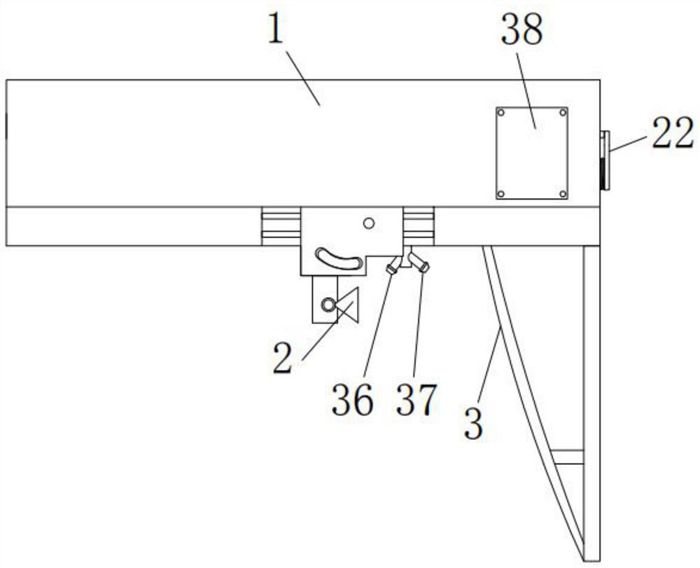
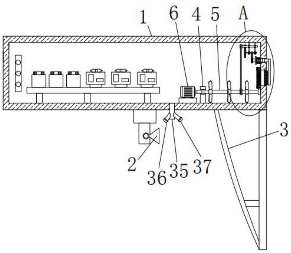
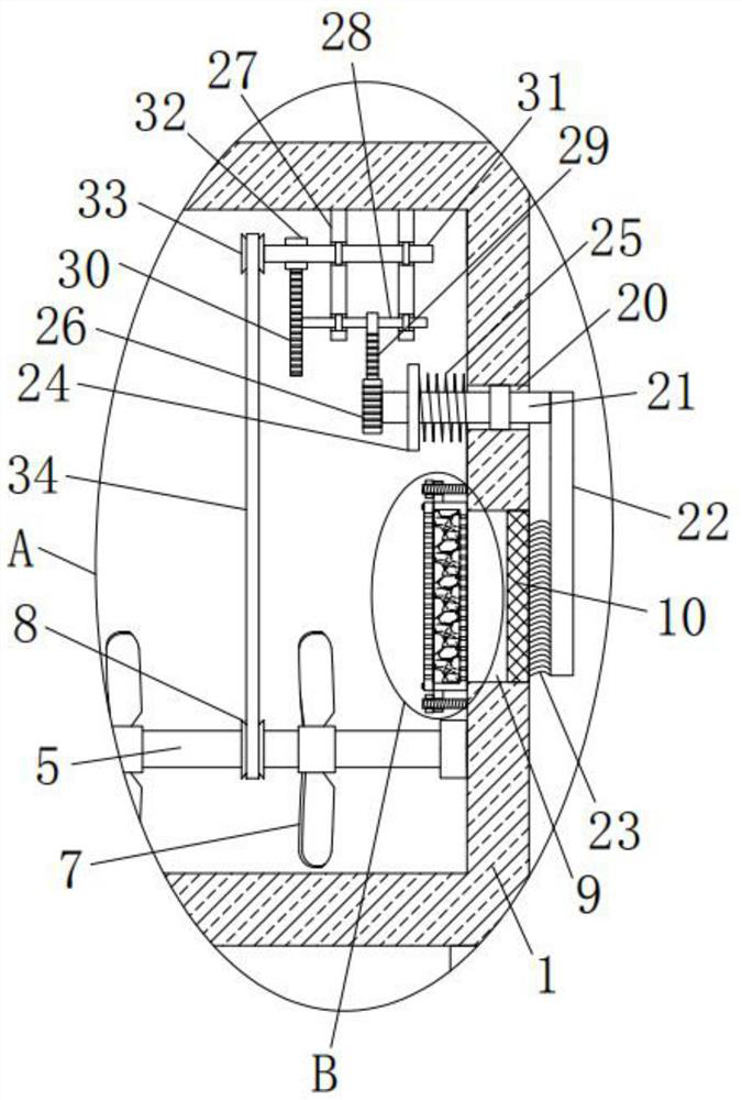
[0029] Such as Figure 1-6 As shown, the present invention provides a technical solution: a projection device for rail transit shielded doors, comprising a projector 1 and a first projection mirror 2 and a second projection mirror 3 installed below the projector 1, and the projection mirror 3 of the projector 1 A fixed base 4 and a motor 6 are fixedly installed on the inner wall of the bottom, and one side of the fixed base 4 is provided with a mounting hole, an...


PUM


Abstract

The invention discloses a rail transit shielding door projection device which comprises a projector, a first projection reflector and a second projection reflector, wherein the first projection reflector and the second projection reflector are mounted below the projector, a fixing seat and a motor are fixedly mounted on the inner wall of the bottom of the projector, a mounting hole is formed in one side of the fixing seat, and a first rotating shaft is rotatably mounted in the mounting hole. The design is reasonable, the practicality is good, and the interior of the projector can be rapidly and effectively cooled; air entering the projector can be filtered, dried and purified; electrical elements in the projector are prevented from being damaged due to damp; meanwhile, dust on a dustprooffilter screen can be cleaned up, hot air exhausted from the projector can blow away dust on the surfaces of the first projection reflector and the second projection reflector, it is guaranteed that the first projection reflector and the second projection reflector have a good refraction effect, and images projected by the projector are clear.

Description

technical field [0001] The invention relates to the technical field of rail transit, in particular to a projection device for a rail transit screen door. Background technique [0002] The rail transit screen door refers to the glass curtain wall on the platform that surrounds the railway platform and the train landing space. The screen door is installed on the subway platform near the side edge of the track to isolate the platform area from the track area. Train When arriving, open the electric door on the glass curtain wall for passengers to get on and off the train. The main function of the screen door is to prevent accidents caused by people falling off the track, reduce the energy consumption of the station's air conditioning and ventilation system, and reduce the impact of train running noise and piston wind on the station. To provide passengers with a safe and comfortable waiting environment. Nowadays, it is a good way to use the projection display on the screen door a...

Claims


Application Information

Patent Timeline
Patent Type & Authority Applications(China)
IPC IPC(8): G03B21/16G03B21/28G03B21/54B08B1/04B08B5/02B08B13/00B01D53/26B61B1/02
CPCG03B21/16G03B21/28G03B21/54B08B5/02B08B13/00B01D53/261B61B1/02B08B1/32B08B1/12
Inventor 胡宗杨
Owner 胡宗杨
Learn More