Ku/Ka waveband double-frequency conical beam horn antenna

A technology of cone beam and horn antenna, which is applied in the field of Ku/Ka band dual-frequency cone beam horn antenna, can solve the problems of narrow impedance bandwidth, long vertical length of antenna, small size, etc., and achieves wide impedance bandwidth and simple feeding. , compact structure

Active Publication Date: 2020-11-24
NANJING UNIV OF SCI & TECH
View PDF6 Cites 4 Cited by
  • Summary
  • Abstract
  • Description
  • Claims
  • Application Information

AI Technical Summary

Problems solved by technology

The traditional dual-band antenna design mostly uses a coupling branch structure to separate the two frequency bands. The disadvantage of this type of design is that the interval between the two frequency bands is strictly limited, and the antenna has a long longitudinal length and high mass, which does not meet the needs of small size, light weight requirements
[0005] Document 3 (Shi-Shan Qi, Wen Wu and Da-Gang Fang. Dual/Single Band Conical-Beam Nested Horn Antennas wit

Method used


Image

  • Ku/Ka waveband double-frequency conical beam horn antenna
  • Ku/Ka waveband double-frequency conical beam horn antenna
  • Ku/Ka waveband double-frequency conical beam horn antenna

Examples


Embodiment 1

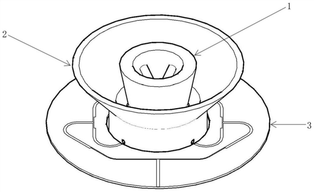
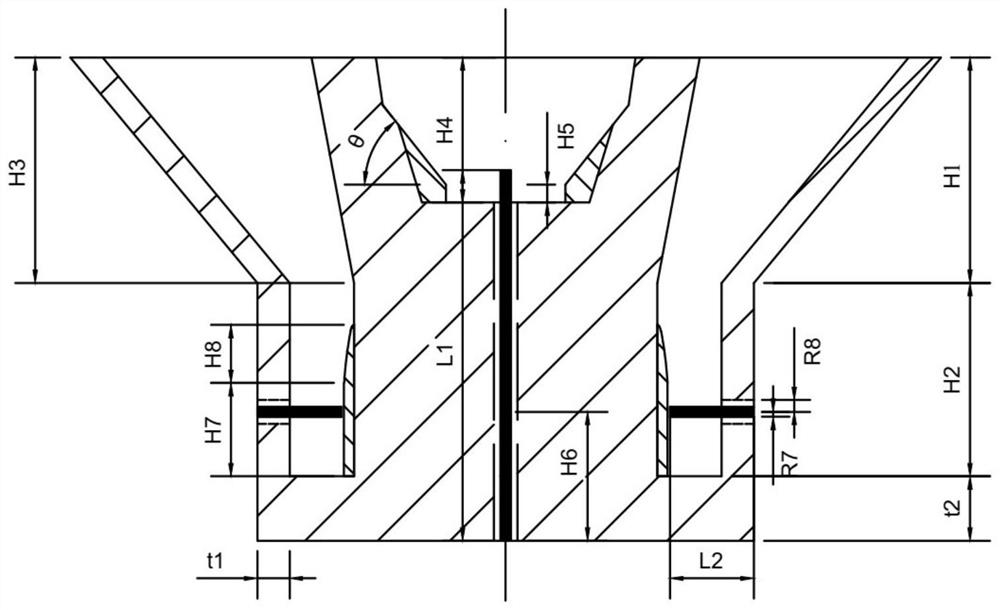
[0048] like Figure 1-5 As shown, a Ku / Ka band dual-frequency conical beam horn antenna in this embodiment is characterized in that the antenna structure is composed of a dual-frequency radiation part and a feeding part. The dual-frequency radiation part adopts a nested horn structure, the inner structure is a ridged circular waveguide horn with a working frequency band of Ka band, and the outer structure is a ridged coaxial horn, which is used for the radiation of the Ku-band antenna. The Ka-band antenna feed adopts a coaxial probe structure, and the Ku-band antenna feed is realized by connecting a coaxial probe with a one-to-four microstrip power divider.

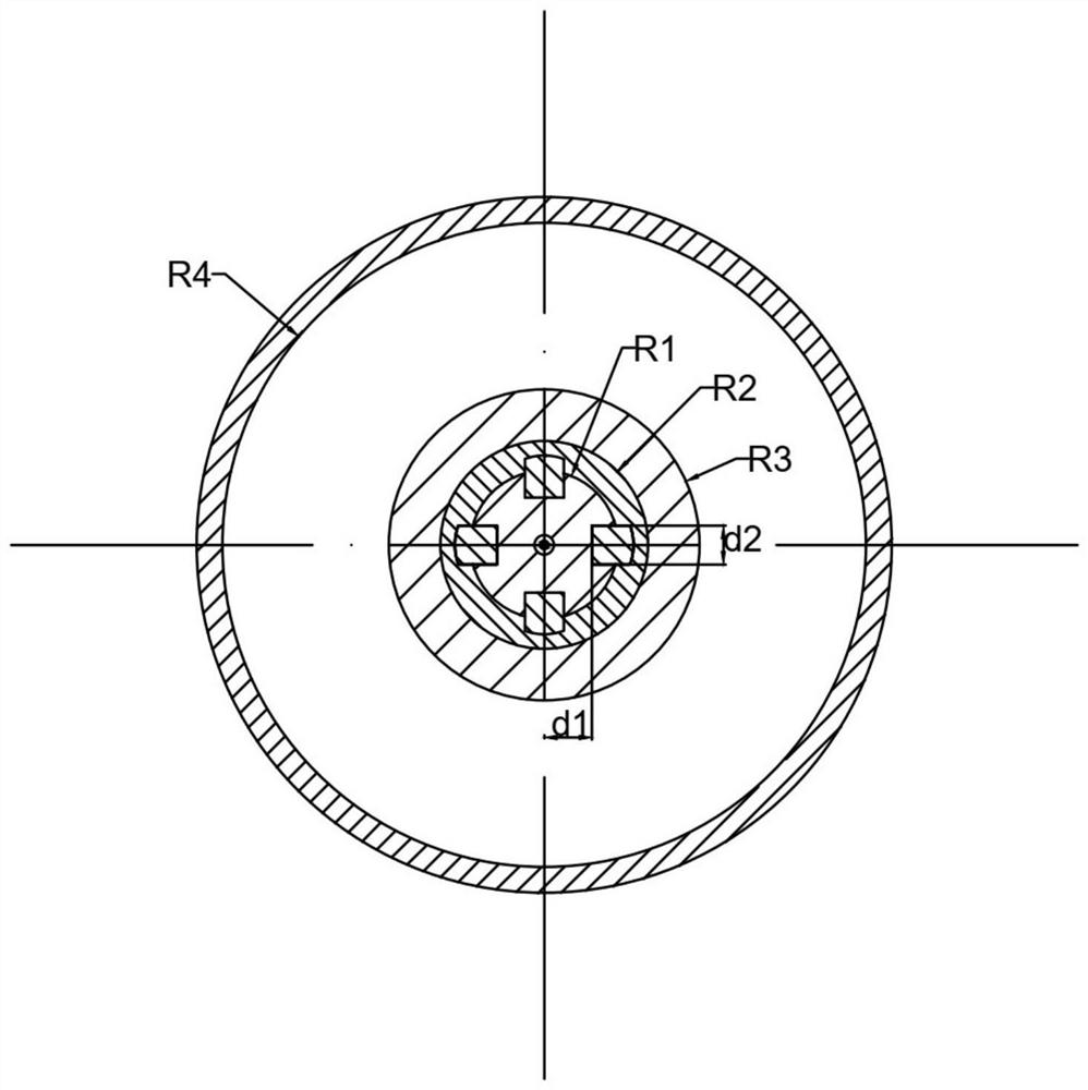
[0049] Ridged circular waveguide horn works in the whole Ka band, coaxial probe excitation, transmission TM 01 mode, suppressing higher-order modes. According to the Open Circuit Circular WaveguideTM 0m The far-field pattern function of the mode, the transmission mode and the radius R of the opening 2 is also related ...


PUM

PropertyMeasurementUnit
Radiusaaaaaaaaaa
Widthaaaaaaaaaa
Heightaaaaaaaaaa

Abstract

The invention discloses a Ku/Ka waveband double-frequency conical wave beam horn antenna. The antenna comprises a double-frequency radiation module and a feed module. The double-frequency radiation module adopts a nested horn structure; the double-frequency radiation module specifically comprises a circular waveguide horn and a coaxial horn nested outside the circular waveguide horn, the working frequency band of the circular waveguide horn is a Ka wave band and used for radiating Ka wave band signals, the working frequency band of the coaxial horn is a Ku wave band and used for radiating Ku wave band signals, and the feeding module is used for feeding the double-frequency radiation module. The radiation pattern of the antenna has conical wave beam characteristics in Ku/Ka wave bands.

Description

technical field [0001] The invention belongs to antenna technology, in particular to a Ku / Ka band dual-frequency conical beam horn antenna. Background technique [0002] The cone beam antenna is a kind of antenna with omnidirectional radiation in the azimuth plane, and the maximum radiation direction of the elevation plane forms a certain cone angle with the normal direction, and the radiation in the normal direction is very small. When detecting air targets, in order to find targets in all directions in time, generally three methods can be adopted: use a higher-gain array antenna for automatic tracking; use a three-dimensional omnidirectional antenna for receiving and transmitting; use a conical beam antenna to Irradiate an area within a certain range of cone angles. The complexity of the array antenna automatic tracking system is very high, and the cost remains high; although the omnidirectional antenna can realize target tracking from all angles, the gain is low. In con...

Claims


Application Information

Patent Timeline
IPC IPC(8): H01Q13/02H01Q5/307H01Q5/20H01Q1/50
CPCH01Q13/02H01Q5/20H01Q5/307H01Q1/50H01Q13/0275
Inventor 吴礼王靖雯彭树生李小柳戈尧林子浩郭曼菲
Owner NANJING UNIV OF SCI & TECH
Why Eureka
Try Eureka