
Assemblable biochemical pool defoaming device and defoaming method

A technology of defoaming device and biochemical pool, applied in chemical instruments and methods, biological water/sewage treatment, degassed water/sewage treatment, etc., can solve the problems of limited foam reduction, high price, secondary environmental pollution, etc. The effect of improving water purification efficiency, improving oxygenation efficiency and reducing foam content

Pending Publication Date: 2020-11-27
YIKANG TECH CO LTD
View PDF0 Cites 0 Cited by
  • Summary
  • Abstract
  • Description
  • Claims
  • Application Information

AI Technical Summary

Problems solved by technology

However, the chemical defoaming method generally has the following problems: secondary pollution to the environment, low defoaming efficiency, high price, etc.
Most of the above-mentioned mechanical defoamers have the following problems in practical application: the processing efficiency is low during use, the foam drop is limited, and the foam with high water content cannot be processed; the liquid produced after foam separation cannot be removed in time, resulting in secondary Foaming, resulting in a more stable secondary foam; poor universality; stirring or centrifugal defoaming process often requires high energy consumption, etc.

Method used


Image

  • Assemblable biochemical pool defoaming device and defoaming method
  • Assemblable biochemical pool defoaming device and defoaming method
  • Assemblable biochemical pool defoaming device and defoaming method

Examples


Embodiment 1

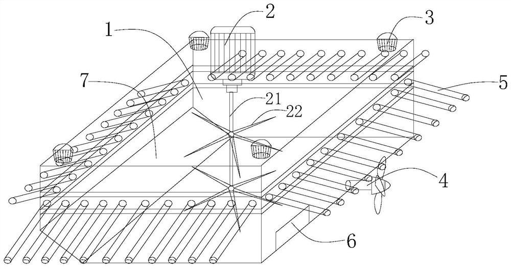
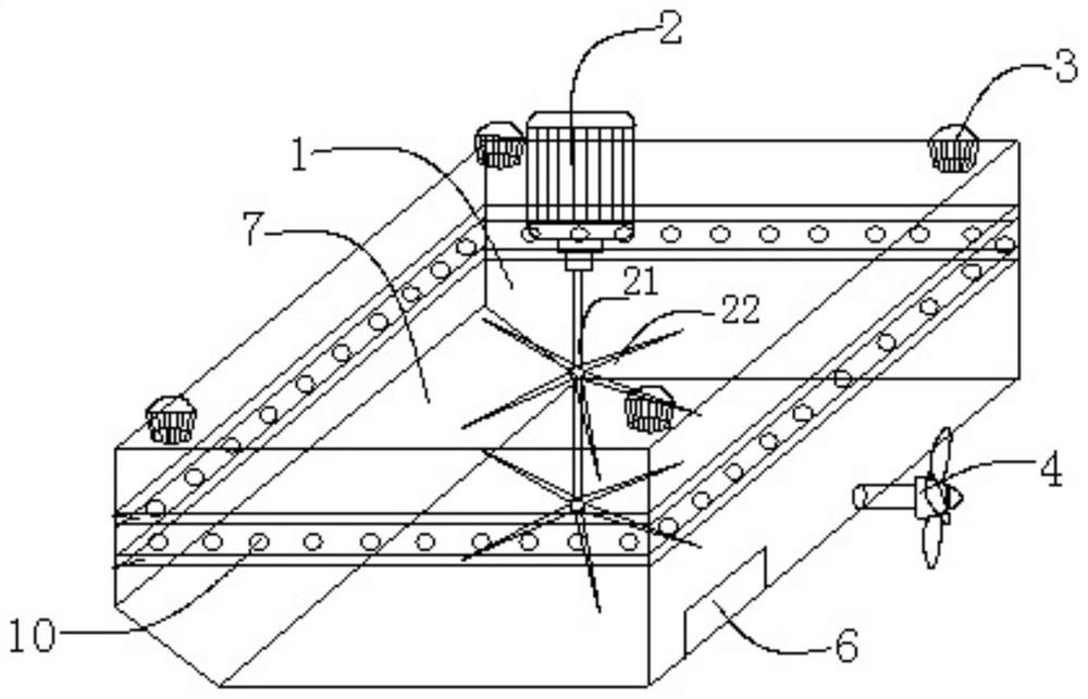
[0038] see figure 1 and figure 2, a biochemical pool defoaming device that can be assembled, including a defoaming unit 1, a foam collecting device and a stirring defoaming device are arranged in the defoaming unit 1, the defoaming unit 1 is designed as a polyhedral structure, and the defoaming unit 1 is designed as a polyhedral structure. A propeller 4 is installed at the driving end of the foam unit 1 , and a wedge plate 7 is arranged inside the defoaming unit 1 , and the installation position of the wedge plate 7 is on the side opposite to the propeller 4 . The propeller 4 is used to drive the defoaming unit 1 to move, and is the power source of the defoaming unit 1 .

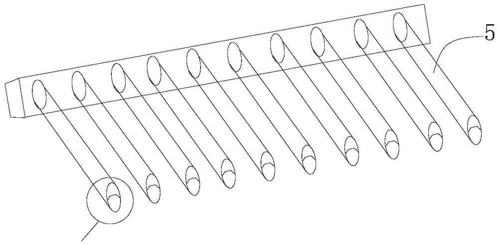
[0039] see figure 1 , image 3 and Figure 5 The foam collecting device is arranged on the side wall of the defoaming unit 1, the stirring and defoaming device is arranged in the inner cavity of the defoaming unit 1, and the foam collecting device includes several foam collecting pipes 5, the defoaming ...

Embodiment 2

[0045] see Figure 4 and Figure 5 , this embodiment serves as a further optimization of Embodiment 1, on the basis of which, adjacent defoaming units 1 can be connected in a front-to-back direction or in a left-right direction ( Figure 7 and Figure 8 As shown), the outer wall of the defoaming unit 1 is provided with connecting guide rails, and the connecting guide rails include an upper slideway 51 and a lower slideway 52, and the upper slideway 51 and the lower slideway 52 are respectively arranged in the built-in foam collection through hole On the upper and lower sides of the position of 10, the upper slideway 51 and the slideway 52 are respectively provided with an upper slideway clamping groove 55 and a slideway clamping groove 56, and the adjacent defoaming units 1 pass through the slideway buckle 54 Butt the corresponding upper slide rail slot 55 or slide rail slot 56 . One side of the foam collecting pipe 5 on the adjacent defoaming unit 1 is set as the slideway ...


PUM


Abstract

The invention relates to the technical field of sewage treatment and relates to an assemblable biochemical pool defoaming device and a defoaming method. The defoaming device comprises a defoaming unit; a foam collecting device and a stirring defoaming device are arranged in the defoaming unit; the defoaming unit is designed into a polyhedral structure; a propeller is mounted at the driving end ofthe defoaming unit; the foam collecting device is arranged on the side wall of the defoaming unit; the stirring defoaming device is arranged in an inner cavity of the defoaming unit; the foam collecting device comprises a plurality of foam collecting pipes; a plurality of built-in foam collecting through holes are formed in the side wall of the defoaming unit; a stirring motor is arranged on the stirring defoaming device; a stirring rod is installed at the driving end of the stirring motor; a plurality of stirring paddles are installed on the stirring rod; and a foam warning line is arranged in the defoaming unit. Any chemical defoaming agent does not need to be added, the foam content of a biochemical pool can be effectively reduced, the oxygenation efficiency is improved, and the water purification efficiency is improved.

Description

technical field [0001] The invention relates to the technical field of sewage treatment, in particular to an assembleable biochemical pool defoaming device and a defoaming method. Background technique [0002] When biochemical treatment of sewage, due to various factors such as sludge residence time, PH value, dissolved oxygen, temperature, etc., a large amount of foam will be generated in the water treatment tank. These foams will have a certain viscosity and will hinder oxygen from entering the exposure. The mixed liquid of the gas pool will reduce the oxygenation efficiency, increase the content of suspended solids in the effluent, and cause many hazards such as deterioration of the effluent quality. At present, the countermeasures to control foam mainly include: spraying water to increase surface agitation, adding bactericide or defoamer, but the effect of the agent can only reduce the growth of foam, but cannot eliminate the formation of foam and reduce the sludge age. ...

Claims


Application Information

Patent Timeline
Patent Type & Authority Applications(China)
IPC IPC(8): C02F1/20C02F3/00
CPCC02F1/20C02F3/00C02F2201/002
Inventor 郝进伟曲毅丁宇杨宏旺徐慧荟刘雪张华巍王兆选张培杨谢辉李守伟于海深常安金田宗康琦李鹏梁春花柳晓明马吉飞牟玉明裴俊玲任国杰杨建成宋晓琳孙国剑王翠辉吴晓峰刘丽肖洪钢武伟臧岐山张广为张来君赵伟龙张林杨小明朱恩祖王强张德亮郑勇
Owner YIKANG TECH CO LTD
Learn More