Injection module for reducing agent

A technology of injection module and reducing agent, which is applied in exhaust gas treatment, mechanical equipment, engine components, etc., can solve the problems of inability to generate large penetration depth, narrow spray cone, and release, etc., and achieve high injection speed and low cost. , the effect of uniform preparation

Pending Publication Date: 2020-11-27
ROBERT BOSCH GMBH
View PDF1 Cites 0 Cited by
  • Summary
  • Abstract
  • Description
  • Claims
  • Application Information

AI Technical Summary

Problems solved by technology

However, such reducing agent jets have the disadvantage that the released spray cone has only a narrow angle and cannot be released over a wide uniform angle
However, larger droplets with a large penetration depth cannot be produced, making jet valves not optimally suited for such applications

Method used


Image

  • Injection module for reducing agent
  • Injection module for reducing agent
  • Injection module for reducing agent

Examples


Embodiment Construction

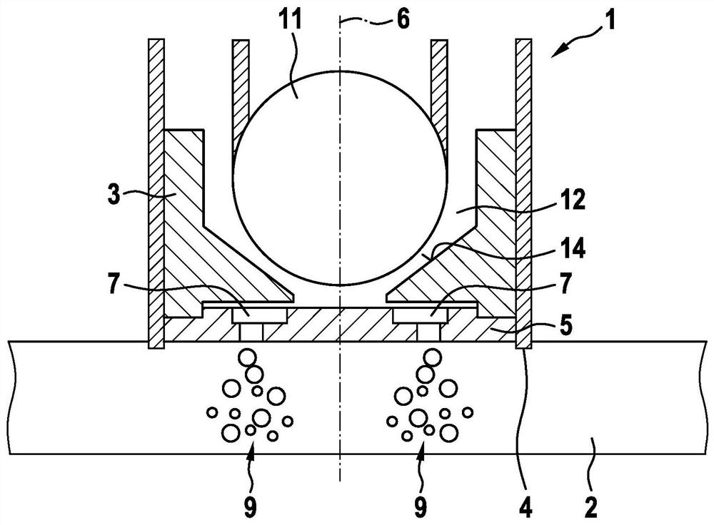
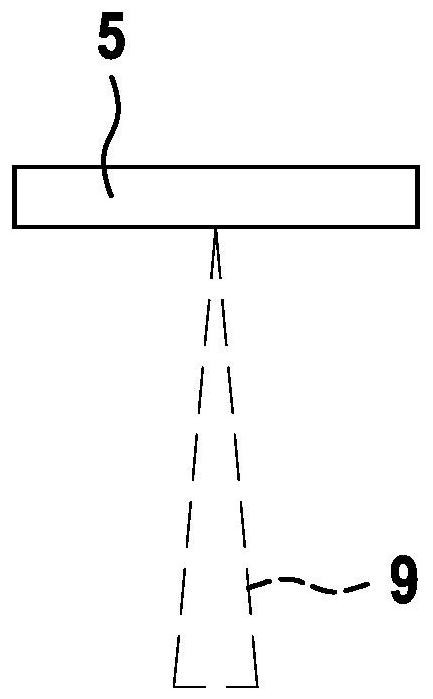
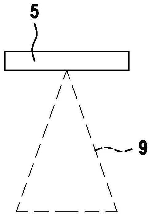
[0021] exist figure 1 shows an injection module, as it is used to introduce reducing agent into the exhaust system of an internal combustion engine. The injection module 1 has a housing 3 which engages in an opening 4 in the wall of the exhaust system 2 . The housing 3 has a reducing agent chamber 12 in which reducing agent is kept under injection pressure. Furthermore, a valve element 11 is arranged longitudinally displaceable in the reducing agent chamber 12 , which here is spherical in shape and cooperates with a valve seat 14 for opening and closing the flow cross section. The housing 3 is delimited at its end facing the exhaust system 2 by an injection disk 5 . The injection disk 5 is designed as a circular or rectangular plate and has two injection openings 7 which are formed in the injection disk 5 opposite to each other with respect to the longitudinal axis 6 of the injection module 1 . If the valve element 11 is moved away from the valve seat 14 by a mechanism, for...


PUM


Abstract

The invention relates to an injection module (1) for injecting a reducing agent into the exhaust gas system (2) of an internal combustion engine, wherein the injection module (1) has a spray disk (5)with two spray holes (7) for the metered delivery of the reducing agent. The spray holes (7) are aligned such that reducing agent jets (9) emerging through the spray holes (7) partially overlap. The two spray holes (7) are designed as bores in the spray disk (5) and each have a longitudinal axis (8, 8'), wherein the longitudinal axes (8, 8') of the spray holes (7)do not intersect.

Description

technical field [0001] The invention relates to an injection module, which is preferably used for introducing a reducing agent into the exhaust system of a motor vehicle or an internal combustion engine. Background technique [0002] When fuel is combusted in an internal combustion engine, nitrogen oxides are always formed, which are carried away in the exhaust gas flow. In order to reduce these nitrogen oxides, a liquid reducing agent, such as an aqueous urea solution, is injected via a dosing unit into the exhaust pipe of the passenger car or truck. Subsequently, the reducing agent reacts with nitrogen oxides in an SCR selective catalytic reduction and reduces the nitrogen oxides to nitrogen and water. A good mixing of the reducing agent with the exhaust gas is indispensable for a reliable action by introducing the reducing agent into the exhaust system in the form of a corresponding spray. These sprays must match the geometry of the exhaust system in shape and depth. T...

Claims


Application Information

Patent Timeline
Patent Type & Authority Applications(China)
IPC IPC(8): F01N3/20
CPCF01N3/206F01N3/2066F01N2610/1453F01N2610/00Y02T10/12
Inventor M·比格林M·莱昂哈德
Owner ROBERT BOSCH GMBH
Why Eureka
Try Eureka