
Display panel and method of making the same

A display panel and substrate substrate technology, which is applied in manufacturing tools, welding equipment, laser welding equipment, etc., can solve problems such as reduced machine life, cutting failure, and poor wiring, so as to improve reliability, reduce costs, and reduce laser welding. The effect of cutting energy

Active Publication Date: 2022-05-31
SHENZHEN CHINA STAR OPTOELECTRONICS SEMICON DISPLAY TECH CO LTD
View PDF0 Cites 0 Cited by
  • Summary
  • Abstract
  • Description
  • Claims
  • Application Information

AI Technical Summary

Problems solved by technology

[0003] The embodiment of the present application provides a display panel and its preparation method to solve the problem that in the existing display panel, when the Shorting bar is laser cut, high energy is required to cut off the organic film and the metal circuit, resulting in a reduction in the life of the machine, and There is a problem of cutting failure, which leads to technical problems of poor wiring

Method used


Image

  • Display panel and method of making the same
  • Display panel and method of making the same
  • Display panel and method of making the same

Examples


Embodiment Construction

[0034] The following disclosure provides many different embodiments or examples for implementing different structures of the present application. for

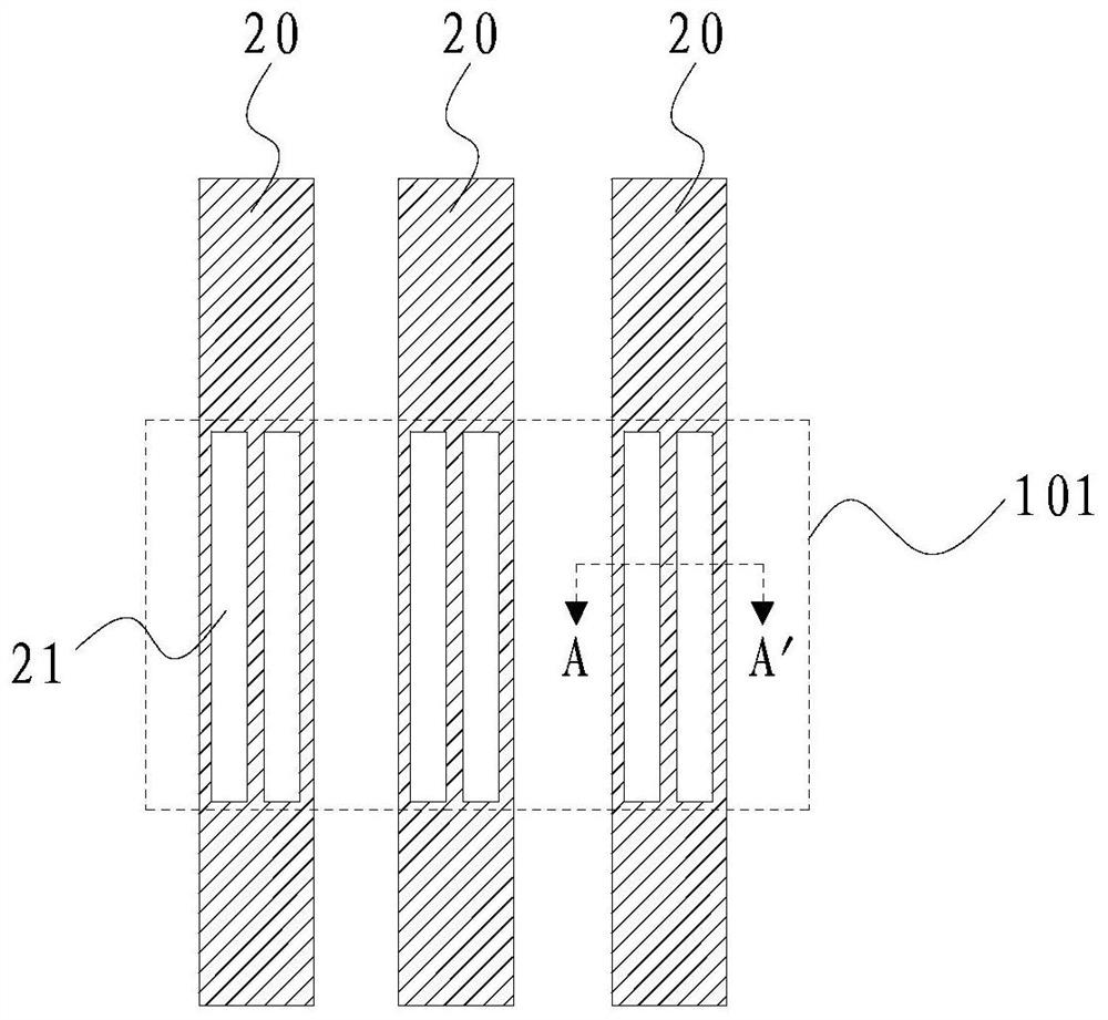
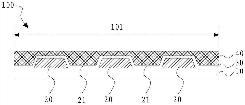
[0035] Please refer to FIG. 1 and FIG. 2, an embodiment of the present application provides a display panel 100, including a base substrate 10, arranged on

[0038] In the embodiment of the present application, the portion of the shorting bar 20 located in the cutting area 101 is patterned and designed.

[0039] Specifically, the shorting bar 20 may include at least one slit-shaped opening 21, and the slit-shaped opening 21 is located at the

[0041] It can be understood that, in other embodiments, the portion of the shorting bar 20 located in the cutting area 101 may be

[0042] Please refer to FIG. 1, in an embodiment, the organic flat layer 40 can completely cover the shorting bar 20.

[0043] Please refer to FIG. 3, in other embodiments, the organic flat layer 40 includes a first groove 41, the first groove

[0045] When the cutt...


PUM


Abstract

A display panel, on which a cutting area is defined, the display panel includes a base substrate, a shorting bar arranged on the base substrate, and an organic planar layer arranged on the shorting bar, the shorting bar includes at least one slit-shaped opening, A slit-like opening is located in the cutting area. By designing the part of the cutting area corresponding to the shorting bar to have a structure with a slit-like opening, the cutting process is made easier, thereby reducing laser cutting energy and cost, and removing part or all of the organic flat layer corresponding to the shorting bar, The laser cutting energy can be further reduced, and the reliability of the laser cutting process can be improved at the same time.

Description

Display panel and method of making the same technical field [0001] The present application relates to the field of display technology, and in particular, to a display panel and a preparation method thereof. Background technique [0002] In order to find abnormal display in advance of the liquid crystal display in the manufacturing process, it is usually drawn in the Cell (liquid crystal cell) section. For quality inspection, a Shorting bar structure is generally designed for image quality inspection. Perform COF on the display module (Chip on Film, chip on film) The shorting bar line needs to be cut off before bonding. However, at present, for liquid crystal display Under the requirements of high resolution and high refresh frequency of the monitor, the metal film thickness is continuously increasing, and the organic film layer technology is widely used in the industry. It requires high laser (laser) energy to cut off the organic film and metal lines, resulting in a ...

Claims


Application Information

Patent Timeline
Patent Type & Authority Patents(China)
IPC IPC(8): H01L23/58H01L23/544H01L21/768G02F1/1333B23K26/38B23K101/40
CPCH01L23/585H01L21/76894H01L22/32G02F1/133351B23K26/38B23K2101/40
Inventor 宋利旺高冬子
Owner SHENZHEN CHINA STAR OPTOELECTRONICS SEMICON DISPLAY TECH CO LTD
Learn More