Safety protection cable trench for communication base station

A technology for safety protection and communication base station, which is applied in the field of safety protection cable trenches for communication base stations, can solve the problems of deposition of rainwater and high temperature of cable trenches, and achieves the effect of ensuring safety, reducing maintenance costs and having good safety protection performance.

Active Publication Date: 2020-12-01
国网黑龙江省电力有限公司七台河供电公司 +1
View PDF9 Cites 3 Cited by
  • Summary
  • Abstract
  • Description
  • Claims
  • Application Information

AI Technical Summary

Problems solved by technology

[0005] The purpose of the present invention is to provide a safety protection cable trench for communication base stations that can stably and effectively protect the cables in view of the above-mentioned problem that the temperature in the cable trench is high and rainwater is often deposited at the bottom

Method used


Image

  • Safety protection cable trench for communication base station
  • Safety protection cable trench for communication base station
  • Safety protection cable trench for communication base station

Examples


Embodiment 1

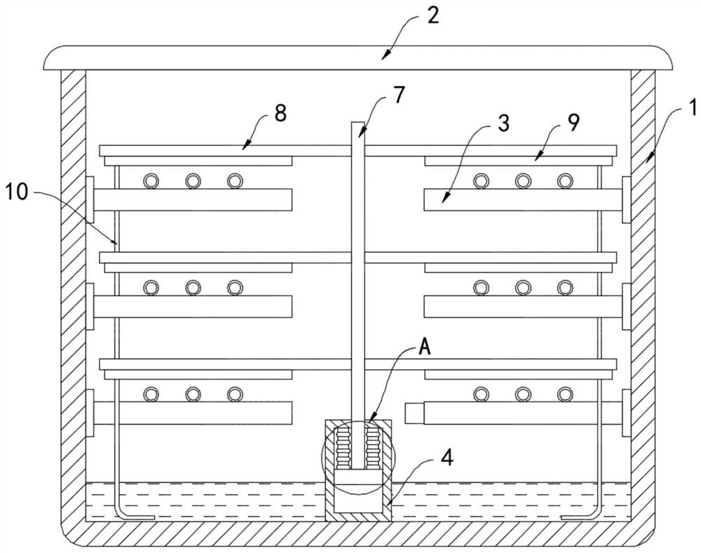
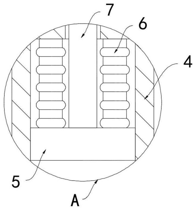
[0021] Such as Figure 1-2 As shown, a safety protection cable trench for a communication base station includes a trench body 1 and a cover plate 2. A plurality of cable racks 3 are equidistantly installed on the side walls on both sides of the trench body 1, and a tube is fixedly installed at the bottom of the trench body 1. Shaped housing 4, the inner side wall of the cylindrical housing 4 is slidingly connected with a slider 5, the upper end of the slider 5 is fixedly connected with the top surface of the cylindrical housing 4 through an elastic bellows 6, and the elastic bellows 6 is filled with Thermal expansion and contraction medium, the thermal expansion and contraction medium is one or more of kerosene, mercury and dichloromethane, expands when heated, shrinks when the temperature drops, and the elastic bellows 6 is surrounded by heat-conducting wires, heat-conducting metal The other end of the wire extends to the cable rack 3, and the heat-conducting metal wire can q...

Embodiment 2

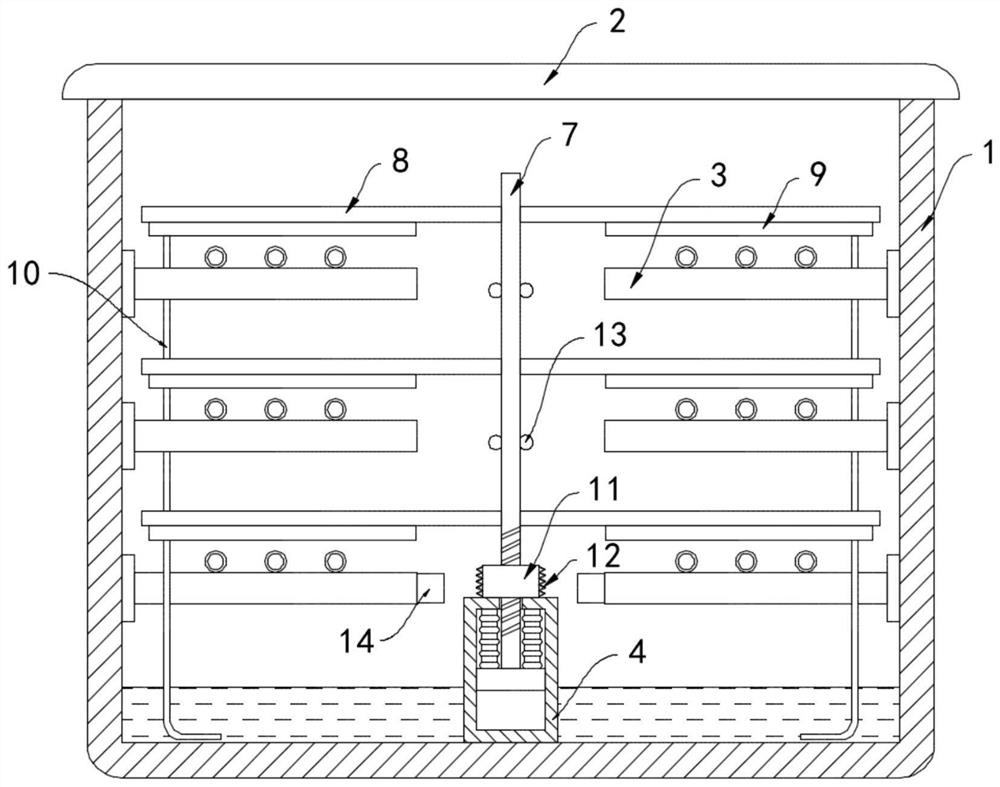
[0026] Such as image 3 As shown, the difference between this embodiment and Embodiment 1 is that the upper end of the tubular housing 4 is rotatably connected with a threaded sleeve 11, the surface of the elevating rod 7 is provided with threads and is threadedly matched with the threaded sleeve 11, and the threaded sleeve 11 is threaded. A multi-turn closed coil 12 is wound on the side wall, and an insect repelling lamp 13 is installed on the surface of the lifting rod 7. A permanent magnet block 14 is installed at one end, and the winding direction of the closed coil 12 is perpendicular to the direction of the magnetic field line of the permanent magnet block 14 .

[0027] In this embodiment, when the lifting rod 7 moves up and down, it drives the threaded sleeve 11 that is threaded with it to rotate, and the closed coil 12 rotates accordingly, and the closed coil 12 continues to cut the magnetic induction of the permanent magnet block 14 during the rotation process. Accor...


PUM


Abstract

The invention belongs to the field of communication facilities, and concretely relates to a safety protection cable trench for a communication base station. The trench comprises a trench body and a cover plate; a plurality of cable racks are mounted on the side walls of the two sides of the trench body at equal intervals; a cylindrical shell is fixedly mounted at the bottom of the trench body; a sliding block is connected to the inner side wall of the cylindrical shell in a sliding manner; the upper end of the sliding block is fixedly connected with the top surface of the cylindrical shell through an elastic corrugated pipe; the elastic corrugated pipe is filled with a thermal expansion and cold contraction medium; and a vertically-arranged lifting rod is fixedly connected to the upper surface of the sliding block, the upper end of the lifting rod penetrates through the top face of the cylindrical shell, a plurality of supporting plates are installed on the side wall of the lifting rodat equal intervals, the plurality of supporting plates extend to the positions above the plurality of cable frames correspondingly, and a sponge water absorption layer is bonded to the lower surfacesof the supporting plates. According to the cable trench, the cable can be cooled, meanwhile, the water removal effect is achieved, manual water removal and cooling work is not needed, and the maintenance cost of the cable trench is reduced.

Description

technical field [0001] The invention belongs to the field of communication facilities, in particular to a safety protection cable trench for a communication base station. Background technique [0002] The communication base station is the most critical infrastructure in the mobile communication network. Most of the existing communication base stations are installed in the open air. A large number of communication and power cables need to be arranged in the cable trench to prolong the service life of the cables and ensure the safe and stable operation of the communication network. . [0003] Most of the traditional cable trenches are equipped with a cover plate, the interior of the trench body is relatively sealed, and the heat dissipation effect is poor. The cable generates a lot of heat during operation, and it is difficult to dissipate the heat in time. The high temperature will easily lead to rapid aging of the cable insulation skin. There may even be a fire; the cable t...

Claims


Application Information

Patent Timeline
Patent Type & Authority Applications(China)
IPC IPC(8): H02G9/02F26B5/16A01M29/10
CPCH02G9/02F26B5/16A01M29/10
Inventor 段江南周倩倩
Owner 国网黑龙江省电力有限公司七台河供电公司
Why Eureka
Try Eureka