Implanting instrument with bionic micro-thorn attachment structures

A device and thorn root technology, applied in the field of implanted devices with bionic micro-thorn attachment structure, can solve the problems of stent vessel sliding, human body danger, thick and long barb structure, etc.

Pending Publication Date: 2020-12-04
NINGBO DIOCHANGE MEDICAL TECH CO LTD
View PDF0 Cites 4 Cited by
  • Summary
  • Abstract
  • Description
  • Claims
  • Application Information

AI Technical Summary

Problems solved by technology

However, there are still the following problems: the anchoring strength is insufficient, and the stent is easy to slide relative to the blood vessel, which causes potential danger to the human body; designed, but not widely adaptable to tortuous diseased vessels
[0005] To sum up, whether it is a filter or an intravascular stent, preventing the displacement and sliding of the device in the blood vessel is the primary safety issue. In the structure of the existing device, in order to achieve effective anchoring, a barbed structure is added to facilitate the passage of the device. Puncture into the vessel wall to achieve anchoring, but this barb structure is often rigid, straight and thick, although it increases anchoring to a certain extent, it has the potential to penetrate the vessel wall, cause complications or lead to implantation failure. risk

Method used


Image

  • Implanting instrument with bionic micro-thorn attachment structures
  • Implanting instrument with bionic micro-thorn attachment structures
  • Implanting instrument with bionic micro-thorn attachment structures

Examples


Embodiment 1

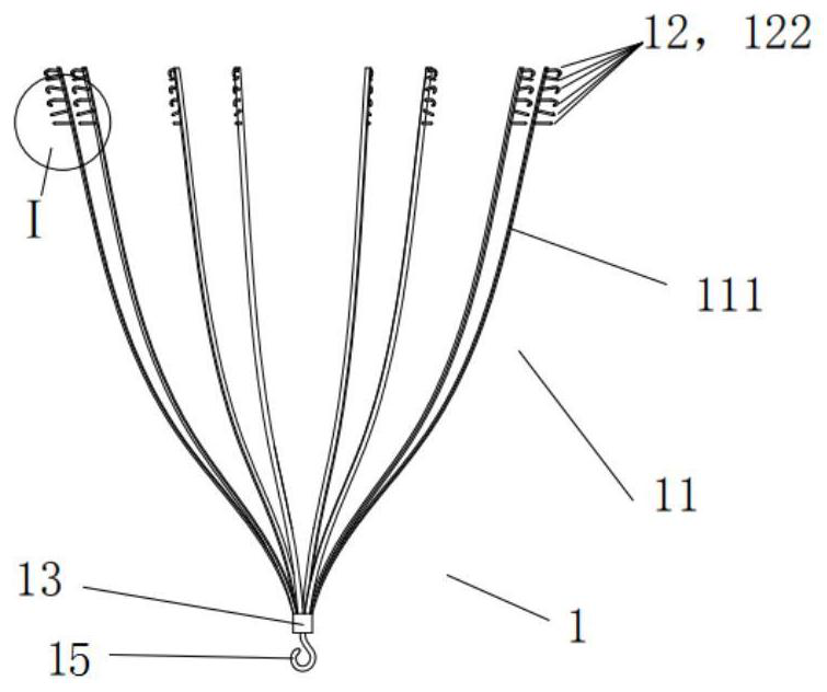
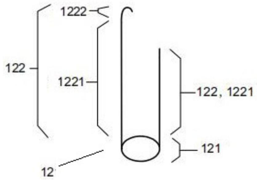
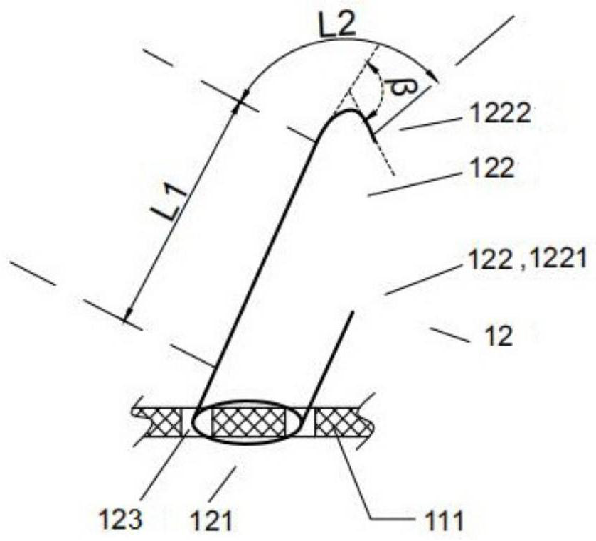
[0112] Such as figure 1 As shown, the implant device 1 provided by the present invention with the bionic micro-thorn attachment structure at least includes an attachment frame 11, and the attachment frame 11 includes a plurality of elastic skeletons 111 and a plurality of bionic micro-thorn attachment structures 12, in a natural unconstrained state , a plurality of skeletons 111 enclose a three-dimensional structure, the attachment frame 11 is adaptive to anatomical form, the bionic micro-thorn attachment structure 12 is arranged on the outer surface of the skeleton 111, and the shape of the bionic micro-thorn attachment structure 12 is imitated on the surface of a plant Sparse microthorns, the bionic microthorn attachment structure 12 includes thorn roots 121 and microthorns 122, the microthorns 122 are composed of sashimi 1221 and thorn points 1222, the microthorns 122 are linear or J-shaped or a combination of both, the microthorns 122 The sashimi 1221 and / or the thorn poin...

Embodiment 2

[0123] refer to Figure 10a and Figure 10b , based on the first embodiment, in the second embodiment, the attachment frame 11 includes a surrounding body 125, the surrounding body 125 is wound on the skeleton 111, and wraps at least the thorns 121 attached to the skeleton 111, for strengthening the skeleton 111 and the connection strength of the bionic microthorn attachment structure 12. The design of the surrounding body 125 also has the following advantages: a) the surrounding body 125 avoids direct contact between part or all of the skeleton 111 and the blood vessel wall, which reduces the precipitation of metal ions and improves biocompatibility; b) reduces the friction coefficient and reduces the adhesion The retraction and release resistance of the frame 11 in the delivery sheath tube 2; c) increase the smoothness, and experience a better hand feeling; d) enhance the fatigue resistance and durability of the attachment frame 11, and play the role of "secondary protectio...

Embodiment 3

[0130] refer to Figure 14 , Compared with Embodiment 1 and Embodiment 2, the difference between Embodiment 3 and Embodiment 1 and Embodiment 2 is that the attachment frame 11 is provided with a self-centered structure 124. In one embodiment, the self-centered structure 124 is located by the skeleton The proximal end and / or the distal end of 111, and is a curly structure formed by the center of the skeleton 111 diverging outward, and the curly structure is one or more of elliptical, circular or two-dimensional helical structures, such as Figure 15 a~ Figure 15 As shown in c, and the plane where each curled structure is located is coplanar with the central axis m, the outer surface of the curled structure is provided with a bionic micro-thorn attachment structure 12, and the sashimi 1221 and / or thorn point 1222 of the bionic micro-thorn attachment structure 12 point to Only on the proximal side, the crimped structure has elasticity and shape memory; in a preferred embodiment...


PUM


Abstract

The invention relates to an implanting instrument with bionic micro-thorn attachment structures. The implanting instrument at least comprises an attachment frame, wherein the attachment frame is a self-expanding type support or a ball-expanding type support and comprises a plurality of frameworks and a plurality of bionic micro-thorn attachment structures; the bionic micro-thorn attachment structures are arranged on the outer surfaces of the frameworks; the bionic micro-thorn attachment structures are in the form of bionic plant surface sparse micro-thorns; each bionic micro-thorn attachment structure comprises a thorn root and a micro-thorn; each micro-thorn is composed of a thorn body and a thorn tip; each micro-thorn is linear or J-shaped or the combination of the linear micro-thorn andthe J-shaped micro-thorn; and the thorn bodies and / or the thorn tips of the micro-thorns can touch cavity tissue to achieve an attachment type anchoring function. The implanting instrument is wide inapplication range, free of anchoring damage, firm and high in safety.

Description

technical field [0001] The invention relates to a medical device, in particular to an implant device with a bionic micro-thorn attachment structure. Background technique [0002] With the rise of interventional surgery, venous filter implantation for pulmonary embolism and endovascular stent implantation for human aortic diseases (such as aortic aneurysm, aortic dissection, etc.) Social concerns. [0003] Venous filter implantation is to implant a temporary filter in the blood vessel, and use the filter to intercept larger thrombus to prevent it from blocking blood vessels in important organs and other places, and to avoid damage to the patient's organs due to hypoxia. An interventional procedure in which the filter is then removed. The common problems of common filters on the market are as follows: the contact area between the support structure and the vessel wall is large, and the filter is easily covered by the vessel intima due to the hyperplasia or adhesion of the ves...

Claims


Application Information

Patent Timeline
Patent Type & Authority Applications(China)
IPC IPC(8): A61B17/12A61F2/07A61F2/06A61F2/01
CPCA61B17/12113A61B17/12159A61B17/12168A61F2/01A61F2/06A61F2/07A61F2002/016A61F2002/061
Inventor 李彪邵烨吕世文
Owner NINGBO DIOCHANGE MEDICAL TECH CO LTD
Why Eureka
Try Eureka