
Clamping and rotating device for thin-wall workpiece

A technology for rotary devices and thin-walled workpieces, applied to broaching devices, accessories of broaching devices, manufacturing tools, etc., can solve problems affecting indexing accuracy and helical interpolation accuracy, large total mass of reciprocating parts, and complex tool systems Overall rigidity and other issues to achieve the effect of ensuring clamping efficiency, compact structure, and small inertia

Active Publication Date: 2020-12-04
德州普利森机床有限公司
View PDF6 Cites 3 Cited by
  • Summary
  • Abstract
  • Description
  • Claims
  • Application Information

AI Technical Summary

Problems solved by technology

[0003] The traditional gun barrel wire drawing machine adopts the method that the workpiece is fixed, the tool reciprocates and rotates along its own axis at the same time. Under this structure, it is difficult to accurately align the workpiece with its own axis, and for titanium alloy thin-walled gun barrels, the opening Composite fixtures are easy to cause clamping deformation
For the tool system, the tool must not only reciprocate, but also realize the rotation and indexing motion along its own axis, resulting in a complex tool system and insufficient overall rigidity, especially for CNC high-precision wire drawing machines. The torsional stiffness of the axis will affect the overall indexing accuracy and helical interpolation accuracy, and because the total mass of the reciprocating parts is too large, the inertia of the main motion system will be large and the response performance will be poor

Method used


Image

  • Clamping and rotating device for thin-wall workpiece
  • Clamping and rotating device for thin-wall workpiece
  • Clamping and rotating device for thin-wall workpiece

Examples


Embodiment Construction

[0027] The present invention will be further explained below in conjunction with the accompanying drawings.

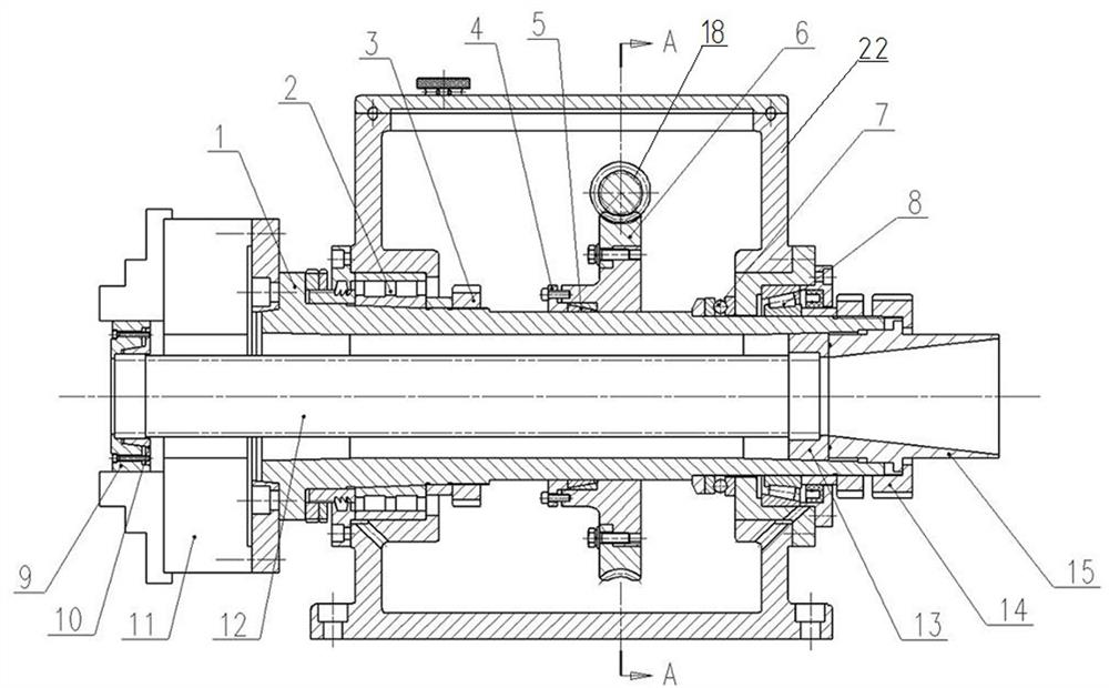
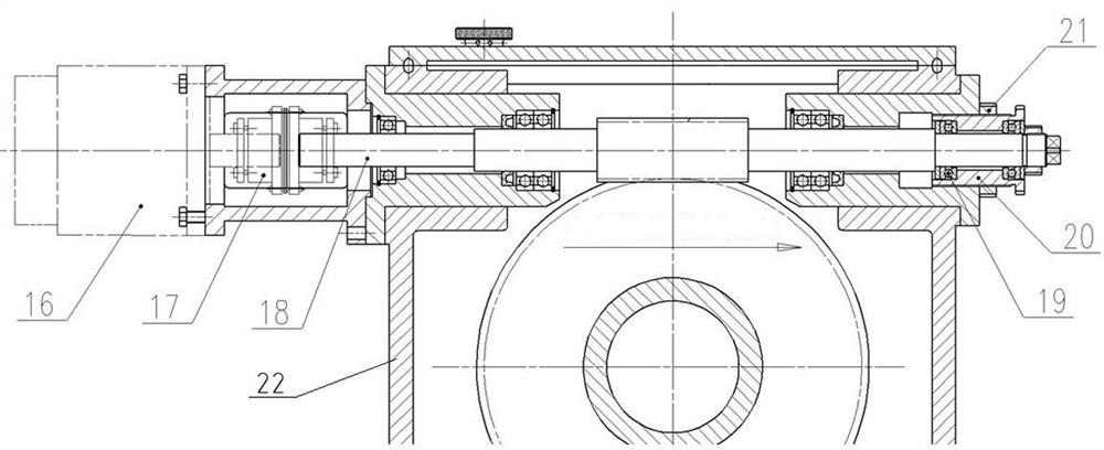
[0028] A clamping and rotating device for thin-walled workpieces, comprising a main shaft 1 provided with an axial center through hole, a transmission box 22, a double-lead worm mechanism and a chuck 11. The double-lead worm mechanism is arranged in the transmission box 22 , and the chuck 11 is installed on the front end surface of the main shaft 1 . The main shaft 1 is installed horizontally on the transmission box 22. The main shaft 1 is clamped by a double-lead worm mechanism and driven to rotate. The workpiece 12 is installed in the main shaft 1. Clamp and rear end are clamped in the central through hole of the main shaft 1. The double-lead worm mechanism includes a worm gear 6 , a double-lead worm 18 meshing with the worm gear 6 and a servo motor 16 .

[0029] The front end of the main shaft 1 is provided with a front bearing 2 and a lock nut I3 to cooperate wit...


PUM


Abstract

The invention relates to machining equipment, in particular to a clamping and rotating device for a thin-wall workpiece. The clamping and rotating device comprises a main shaft with an axial central through hole, a transmission case, a double-lead worm mechanism and a chuck, wherein the main shaft is transversely arranged on the transmission case in a penetrating mode, the main shaft is clamped and driven to rotate by the double-lead worm mechanism, the double-lead worm mechanism is arranged inside the transmission case, and the chuck is arranged on the front end surface of the main shaft; andthe workpiece is arranged inside the main shaft in a penetrating mode, the front end of the workpiece is clamped by the chuck, and the rear end of the workpiece is clamped in the central through holeof the main shaft. The gun barrel workpiece is arranged inside the main shaft hole, and the axis of a gun barrel and the main shaft of the device rotate strictly, coaxially and synchronously throughreliable clamping of the front end and the rear end; and control over high-precision rotating motion of the main shaft is achieved through the double-lead worm and worm gear mechanism, so that numerical control rotating motion according to the rifling winding angle and indexing motion for machining another group of rifling in the wire drawing process are achieved.

Description

technical field [0001] The invention relates to machining equipment, in particular to a clamping and rotating device for thin-walled workpieces. Background technique [0002] With the development of weapon technology, the barrel of the traditional recoilless gun has changed from a smoothbore structure to a rifling structure, and then upgraded from a fixed-angle rifling to a gradual-angle rifling, and the material has also been upgraded from traditional gun steel to titanium alloy materials. , realizing lightweight and easy to carry. The processing of rifling is realized by broaching, and there are two main movements: one is reciprocating movement, and the other is rotational movement. [0003] The traditional gun barrel wire drawing machine adopts the method that the workpiece is fixed, the tool reciprocates and rotates along its own axis at the same time. Under this structure, it is difficult to accurately align the workpiece with its own axis. Composite fixtures are easy...

Claims


Application Information

Patent Timeline
IPC IPC(8): B23D39/00B23D41/06
CPCB23D39/00B23D41/06
Inventor 鲁绪阁齐鹏李革志
Owner 德州普利森机床有限公司
Learn More