Manufacturing process method of valve seat for fracturing pump

A manufacturing process and technology for fracturing pumps, which is applied in the field of valve seat manufacturing process for fracturing pumps, can solve the problems of repair layer peeling, delamination and wear, and unsatisfactory results, so as to improve product life, uniform hardness, and reduce replacement The effect of the number of overhauls

Inactive Publication Date: 2020-12-04
江苏艾福泰克能源装备有限公司
View PDF0 Cites 0 Cited by
  • Summary
  • Abstract
  • Description
  • Claims
  • Application Information

AI Technical Summary

Problems solved by technology

[0005] In order to solve the erosion, pitting, delamination, delamination and other phenomena on the contact surface of the fracturing pump valve seat, the effect is not ideal during the repair process, and problems such as delamination, delamination and wear of the repair layer are prone to occur, which is a technical problem. , the present invention provides a valve seat manufacturing method for fracturing pumps, the technical proposal is specifically: open a concave notch on the surface area of ​​the valve seat blank, and use plasma surfacing welding to surfacing high-strength alloy powder on the In the concave notch, the alloy powder is melted, mixed, diffused, solidified, self-excited and cooled after welding to obtain a high-performance alloy layer for the valve seat of the fracturing pump

Method used


Image

  • Manufacturing process method of valve seat for fracturing pump
  • Manufacturing process method of valve seat for fracturing pump
  • Manufacturing process method of valve seat for fracturing pump

Examples


Embodiment Construction

[0014] The following will further describe the accompanying drawings of the present invention in conjunction with the embodiments.

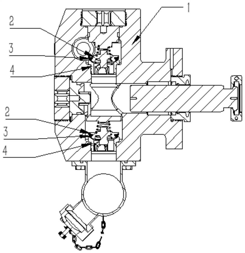
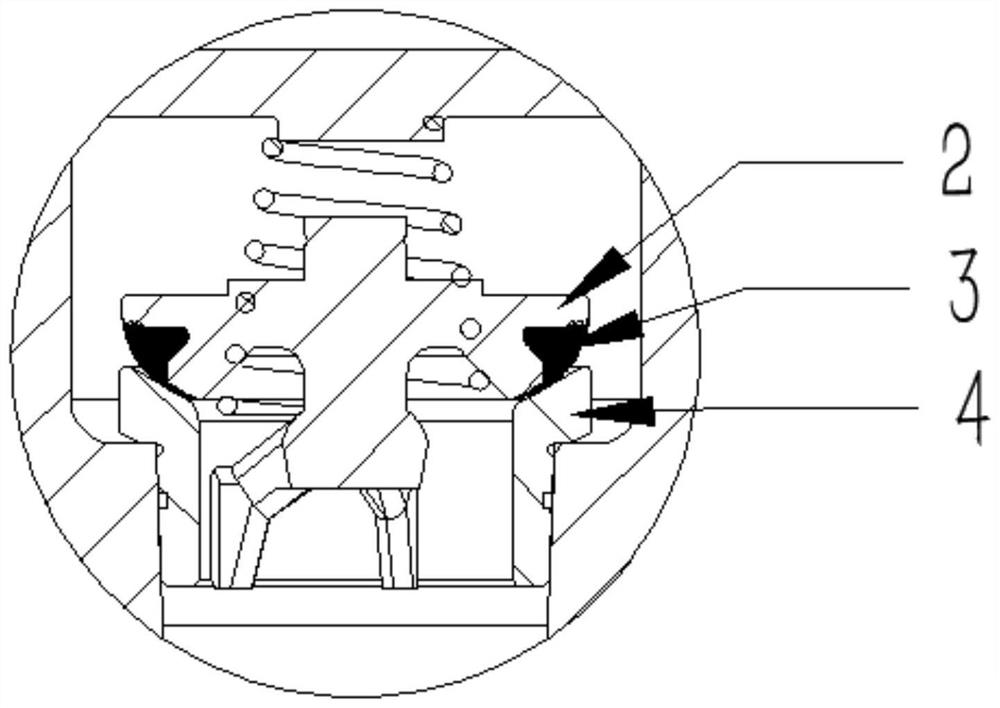
[0015] For the position valve rubber 3 where the valve body 2 of the hydraulic cylinder 1 is in contact with the valve seat 4, wear is prone to occur during the working process. When repairing after wear, the conventional technology is to use surface carburizing treatment to improve the surface hardness, but When the surface hardness meets the requirements, there will be a problem that the hardness will drop sharply with the depth of the carburized layer, and the depth of the carburized layer is shallow, so the service life is low. In order to solve this problem, the welding method of plasma surfacing is used in the present invention. Surfacing repair.

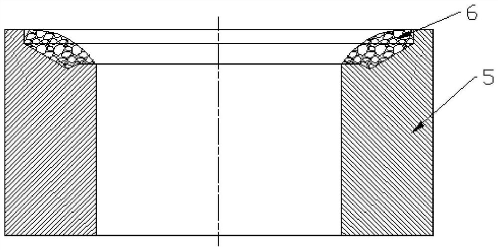
[0016] On the blank of the valve seat 4, a concave groove is left in the contact surface area, and the high-strength alloy powder is surfacing welded in the concave groove by a plasma surfacing p...


PUM

PropertyMeasurementUnit
Thicknessaaaaaaaaaa
Hardnessaaaaaaaaaa

Abstract

The invention provides a manufacturing process method of a valve seat for a fracturing pump. The method comprises the specific steps of forming a concave notch in the surface area of a valve seat blank, performing surfacing on high-strength alloy powder into the concave notch in a plasma surfacing mode to make the alloy powder melted, mixed, diffused and solidified, and performing self-excited cooling after welding to obtain a high-performance alloy layer of the valve seat for the fracturing pump. According to the method, a plasma surfacing process is adopted to replace a traditional carburizing treatment process, the problems that the depth of a carburized layer is low and the hardness sharply decreases along with the depth of the carburized layer in the carburizing process are avoided, the high-hardness depth of the valve seat can reach 2-3 mm, and the hardness is uniform and will not decrease along with surface abrasion. Therefore, the product quality of the valve seat is improved,the product service life of the valve seat is prolonged, the frequency of replacement or maintenance of the fracturing pump is reduced, the labor intensity of workers is reduced, the product reliability is improved, shutdown or pump stop caused by failure in the operation process is avoided, and the shale gas exploitation requirement is better met.

Description

technical field [0001] The invention belongs to the field of machinery manufacturing for oil and gas field stimulation operations and shale gas exploitation fracturing operations, and in particular relates to a manufacturing process for a valve seat for a fracturing pump. Background technique [0002] In oil and gas field stimulation operations and shale gas mining fracturing operations, the fracturing pump is the key equipment. The quality, reliability and life of the fracturing pump directly affect the effect and economic benefits. The valve seat in the fracturing pump accessories is the fracturing pump. An important part in the liquid end of the pump, through the opening and closing of the valve body and the valve seat to realize the inflow and outflow of fluid. The valve body is equipped with a valve rubber made of rubber material. Through the closing and opening of the contact surface between the valve rubber and the valve seat, the fluid enters the hydraulic cylinder o...

Claims


Application Information

Patent Timeline
IPC IPC(8): B23K10/02B23K35/02B23K35/30
CPCB23K10/02B23K35/0255B23K35/304B23K35/3053
Inventor 傅宏伟时圣平姜涌郭志军
Owner 江苏艾福泰克能源装备有限公司
Why Eureka
Try Eureka