Columnar fin falling film evaporation heat exchange tube

A falling-film evaporation and heat-exchange tube technology is applied in the fields of columnar fin falling-film evaporation heat-exchange tubes, falling-film evaporators, and absorbers, and can solve problems such as jeopardizing the safety of connected equipment, steam carry-off, splashing, etc. To achieve the effect of enhancing the boiling heat transfer efficiency, improving the evaporation heat transfer coefficient, and increasing the flow velocity

Pending Publication Date: 2020-12-04
山东恒辉节能技术集团有限公司
View PDF1 Cites 0 Cited by
  • Summary
  • Abstract
  • Description
  • Claims
  • Application Information

AI Technical Summary

Problems solved by technology

However, when the liquid dripping from a high place hits the surface of the heat exchange tube below, splashing will occur. The splashed liquid either directly drops on the bottom of the heat exchanger through the gap between the heat exchange tubes and cannot participate in evaporation, or is randomly The steam is carried away, resulting in uneven liquid distribution locally, which will seriously affect the heat exchange efficiency of the evaporator; even rushing out of the evaporator will endanger the safety of connected equipment

Method used


Image

  • Columnar fin falling film evaporation heat exchange tube
  • Columnar fin falling film evaporation heat exchange tube
  • Columnar fin falling film evaporation heat exchange tube

Examples


Embodiment Construction

[0029] The specific embodiment of the present invention is described in detail below in conjunction with accompanying drawing:

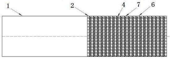
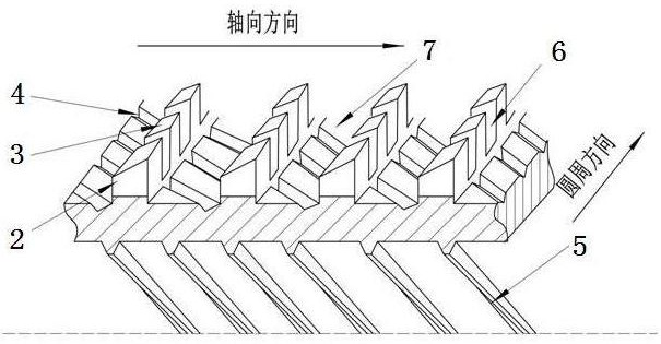
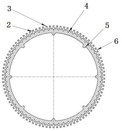
[0030] Such as Figure 1-Figure 6 As shown, a columnar fin falling film evaporation heat exchange tube is The pipe fittings include two parts, the light section 1 and the evaporation surface section. The evaporation surface section is the heat exchange surface. The fins are composed of evenly arranged rectangular columnar fins 2, the rectangular columnar fins 2 are provided with 144 per inch along the axial direction, and the height of the rectangular columnar fins 2 is 0.15-0.5mm (preferably 0.35mm); The aspect ratio of the columnar section is (1.1-4):1, preferably the columnar section of the rectangular columnar fin 2 has a length of 0.57mm and a width of 0.45mm. The top surface 3 of the rectangular columnar fin 2 is an inclined surface, the included angle with the direction of gravity is 30-45 degrees, and the inclined surface faces the axial di...


PUM


Abstract

The invention discloses a columnar fin falling film evaporation heat exchange tube. Rectangular columnar fins are uniformly arranged on the outer surface of the columnar fin falling film evaporation heat exchange tube, axial and circumferential grooves are formed by gaps between the adjacent columnar fins, and a flow network beneficial to uniform distribution of liquid is formed; in order to prevent splashing and surface appearance changing generated when liquid in the upper row of heat exchange tube bodies drips to the surfaces of the lower row of heat exchange tube bodies, the tops of the columnar fins are designed to be inclined planes; a plurality of micro inclined grooves are formed in the bottoms of the circumferential grooves, so that wetting angles are increased, the hydrophobicityof the surface is improved through the combined action of the micro inclined grooves in the bottoms of the grooves and the inclined tops of the columnar fins, and the state of the surface reaches theCassie state of the rough surface; and the liquid flow resistance is reduced, the spreading performance of the liquid is improved, the thickness of a liquid film is reduced, a composite boundary jointly formed by solid, liquid and steam can be further formed, the number of gasification cores is increased, and the evaporation heat exchange coefficient is increased.

Description

technical field [0001] The invention relates to a columnar fin falling film evaporation heat exchange tube, which belongs to the technical field of heat exchangers, and is especially suitable for falling film evaporators, including absorbers in absorption heat pump systems. Background technique [0002] At present, the falling film evaporator is widely used in the evaporator of the central air conditioning system, including the evaporator and absorber of the lithium bromide absorption heat pump. On the arranged heat exchange tubes, part of the liquid generates steam through heat exchange with the hot fluid in the heat exchange tubes, and the other part of the non-evaporated liquid will drop radially along the heat exchange tubes to the tubes arranged below. Since the liquid sprayed by the sprinkler and the liquid dripping from the high heat exchange tube are basically in the shape of drops or columns, the thickness of the local liquid film at the dripping place is greater th...

Claims


Application Information

Patent Timeline
Patent Type & Authority Applications(China)
IPC IPC(8): F28F1/42
CPCF28F1/42
Inventor 李小利王斌马青川李玉海宋辉张俊峰林俊庆
Owner 山东恒辉节能技术集团有限公司
Why Eureka
Try Eureka